
Air knife lip cleaning device

A technology of cleaning device and air knife, which is applied in the direction of metal material coating process, coating, hot-dip plating process, etc., can solve problems such as stuck, small balls are easy to fall off due to heat, and cannot be detected in time, so as to meet the spraying angle Adjustment, full and effective contact, cleaning and scraping smooth effect

Pending Publication Date: 2022-07-08
WUHAN IRON & STEEL BEIHUI DECHENG EQUIP CO LTD
View PDF1 Cites 0 Cited by
  • Summary
  • Abstract
  • Description
  • Claims
  • Application Information

AI Technical Summary

Problems solved by technology

It is an external scraper device with a complex structure. The cylinder drives the sliders on the upper and lower tracks. The main disadvantage is that it is prone to jamming due to the high temperature environment around the zinc pot during work.
Based on this, a built-in structure with the air knife lip cleaning device hidden in the air knife (such as the air knife lip cleaning device imported from abroad) has appeared. The upper rolling ball, in order to ensure the flexible rotation of the rolling ball, requires very high machining accuracy. However, the small ball is easy to fall off due to heat during work. Once the ball falls off, it will cause jamming during the movement of the slider. If it is detected in time, the whole device will be broken under the tension of the wire rope, and the damage rate is very high
As a result, the demand for imported spare parts has greatly increased

Method used


Image

  • Air knife lip cleaning device
  • Air knife lip cleaning device
  • Air knife lip cleaning device

Examples


Embodiment Construction

[0021] The embodiments of the present invention are further described below with reference to the accompanying drawings, examples of which are shown in the accompanying drawings, wherein the same or similar reference numerals represent the same or similar elements or elements with the same or similar functions throughout. The embodiments described below by referring to the accompanying drawings are exemplary and are intended to be used to explain the present invention, but should not be construed as a limitation of the present invention, and any modifications, equivalent replacements, or Improvements and the like should all be included within the scope of the claims of the present invention, and those not described in detail in this technical solution are all known technologies.

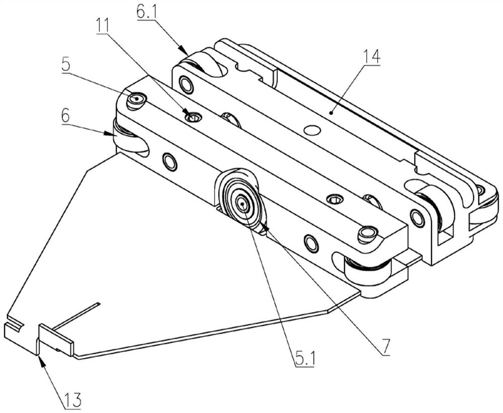
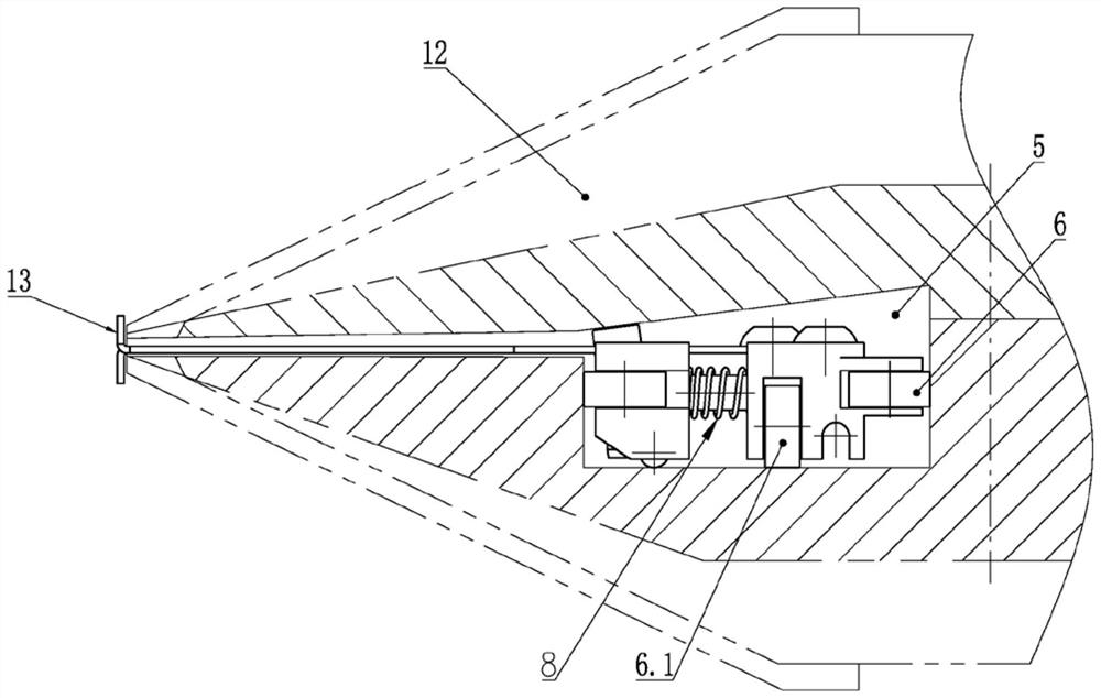
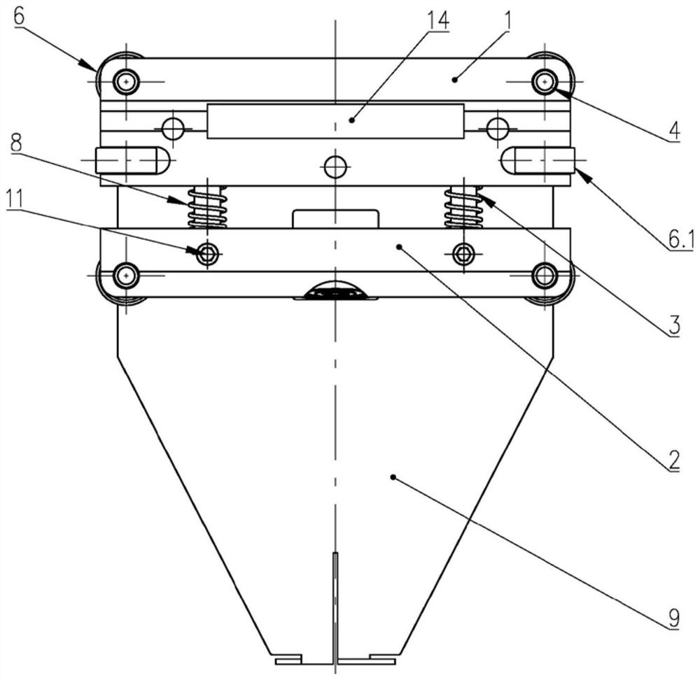
[0022] see Figure 1 to Figure 5 , an air knife lip cleaning device of the present invention includes: a rectangular parallelepiped base body composed of A sliding seat 1 and B sliding seat 2, the ba...


PUM


Abstract

The invention designs an air knife lip cleaning device which comprises a base body composed of a sliding seat A and a sliding seat B. The base body can move left and right in a guide rail groove of an air knife body in a reciprocating mode. The lower side of the sliding seat A is fixedly connected with a scraper used for cleaning an air knife lip, the part, extending out of the air knife lip, of the front end of the scraper is provided with a vertical knife lip scraping piece, and the knife lip scraping piece is in sliding contact with the air knife lip under pressure; a rolling bearing is arranged on the contact surface of the base body and the guide rail groove; a spring shaft extending into the front surface of the sliding seat A is fixedly connected to the rear surface of the sliding seat B, the outer circle of the spring shaft is sleeved with a pressure spring, and the front portion of the extending end of the spring shaft can freely slide in the sliding seat A. During working, the scraper body covers the outer surface of the lip, the cleaning effect is not affected by a gap of the lip, the fault that the cleaner is clamped in the lip can be avoided, the cleaning efficiency is improved, the service life is prolonged, and the scraper replaces import to be applied to domestic large iron and steel enterprises, and the good effect is achieved.

Description

technical field [0001] The invention relates to an air knife lip cleaning device, in particular to a cleaning device used on the air knife lip, which is a key equipment on a continuous hot-dip galvanizing production line in the iron and steel industry, and is used for cleaning the metal residues attached to the air knife nozzle, It belongs to the technical field of metallurgical equipment. Background technique [0002] In the continuous galvanizing line of cold-rolled strip steel in the metallurgical industry, the air knife device is the key process equipment. The device sprays a continuous flat air flow like a knife on the surface of the galvanized steel strip to scrape off the excess zinc liquid on the surface of the steel strip before solidification, so as to realize the control of the thickness and surface quality of the galvanized layer on the surface of the steel strip. . Since the air knife device is arranged above the zinc pot containing the molten zinc liquid, the...

Claims


Application Information

Patent Timeline
IPC IPC(8): C23C2/20
CPCC23C2/20Y02P10/20
Inventor 黄辉余振华张博罗凯
Owner WUHAN IRON & STEEL BEIHUI DECHENG EQUIP CO LTD
Learn More