Gravity compressed air energy storage system

A technology of compressed air energy storage and gravity, applied in wind power generation, steam engine installations, liquid variable capacity machinery, etc., can solve the problems of too high gravity block height and increased construction difficulty.

Active Publication Date: 2022-07-08
XIAN THERMAL POWER RES INST CO LTD +1
View PDF10 Cites 0 Cited by
  • Summary
  • Abstract
  • Description
  • Claims
  • Application Information

AI Technical Summary

Problems solved by technology

[0002] Gravity compressed air energy storage is by setting a gravity block in the shaft, the gravity block and the shaft are sealed and connected by a sealing film, and a sealed gas storage chamber is formed in the shaft below the gravity block for the storage of high-pressure gas. After compression, it is passed into the air storage chamber to convert the energy of the compressed air into the gravitational potential energy of the gravity block for storage. However, when the storage capacity is large, a gravity block with a larger weight is needed, and the gravity can be directly increased by adjusting the height of the gravity block When the weight of the block is too large, the construction difficulty will be increased if the height of the gravity block is too large

Method used


Image

  • Gravity compressed air energy storage system
  • Gravity compressed air energy storage system

Examples


Embodiment Construction

[0027] The following describes in detail the embodiments of the present application, examples of which are illustrated in the accompanying drawings, wherein the same or similar reference numerals refer to the same or similar elements or elements having the same or similar functions throughout. The embodiments described below with reference to the accompanying drawings are exemplary and are only used to explain the present application, but should not be construed as a limitation on the present application. On the contrary, the embodiments of the present application include all changes, modifications and equivalents falling within the spirit and scope of the appended claims.

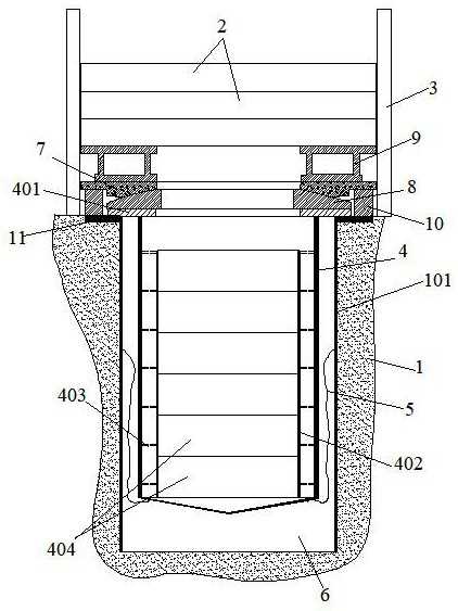
[0028] figure 1 It is a schematic structural diagram of a gravity compressed air energy storage system proposed in an embodiment of the present application.

[0029] see figure 1 , a gravity compressed air energy storage system, including a shaft 1, a first-level gravity block 2 and a plurality of guide ...


PUM


Abstract

The invention provides a gravity compressed air energy storage system which comprises a vertical shaft, a primary gravity block and a plurality of guide rails, a pressure-bearing cylinder is movably inserted into the vertical shaft, and a locking assembly is arranged at the top end of the pressure-bearing cylinder, so that the pressure-bearing cylinder is supported on the ground at the top of the vertical shaft through the locking assembly at the lowest limit; the first-stage gravity block is arranged above the locking assembly, a spherical connecting assembly is arranged between the first-stage gravity block and the locking assembly, the first-stage gravity block and the locking assembly are in spherical connection through the spherical connecting assembly, and a plurality of guide assemblies are arranged on the peripheral side of the first-stage gravity block; the multiple guide rails are arranged on the ground and on the peripheral side of the first-stage gravity block, the guide rails are matched with the guide assembly, the first-stage gravity block is limited through the multiple guide rails, the gravity is divided into an overground part and an underground part, the weight of the gravity block needed by gas storage can be increased through the overground part, and the height of the vertical shaft is reduced; and the excavation work amount and the engineering difficulty of the vertical shaft are greatly reduced.

Description

technical field [0001] The present application relates to the technical field of electrical energy storage, and in particular, to a gravity compressed air energy storage system. Background technique [0002] Gravity compressed air energy storage is to set a gravity block in the shaft, the gravity block and the shaft are sealed and connected by a sealing film, and a sealed air storage cavity is formed in the shaft under the gravity block for the storage of high-pressure gas. After compression, it is passed into the air storage chamber to convert the energy of the compressed air into the gravitational potential energy of the gravity block for storage. However, when the storage capacity is large, a larger weight gravity block is required, and the gravity is directly increased by adjusting the height of the gravity block. When the weight of the block is too large, the height of the gravity block will increase the difficulty of construction. SUMMARY OF THE INVENTION [0003] T...

Claims


Application Information

Patent Timeline
Patent Type & Authority Applications(China)
IPC IPC(8): F01K27/00F04B41/02F03G3/00
CPCF01K27/00F04B41/02F03G3/00Y02E10/72
Inventor 文军李阳赵瀚辰杨成龙姬海民宋晓辉秦海峰黄海威刘树昌于在松
Owner XIAN THERMAL POWER RES INST CO LTD
Why Eureka
Try Eureka