
Hydraulic damper

A technology of hydraulic dampers and hydraulic cylinders, which is applied to liquid shock absorbers, shock absorbers, shock absorbers, etc., and can solve problems such as inability to adjust the damping coefficient

Pending Publication Date: 2022-07-08
龚颖
View PDF0 Cites 0 Cited by
  • Summary
  • Abstract
  • Description
  • Claims
  • Application Information

AI Technical Summary

Problems solved by technology

[0005] The damping coefficient of the damper will only jump between two values, one large and one small, instead of a gradual transition from a small value to a large value, and the damping coefficient cannot be adjusted

Method used


Image

  • Hydraulic damper
  • Hydraulic damper

Examples


Embodiment Construction

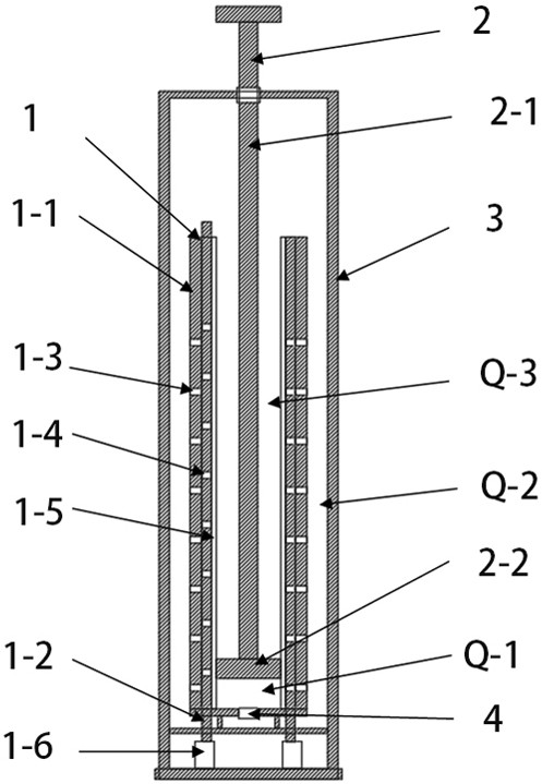
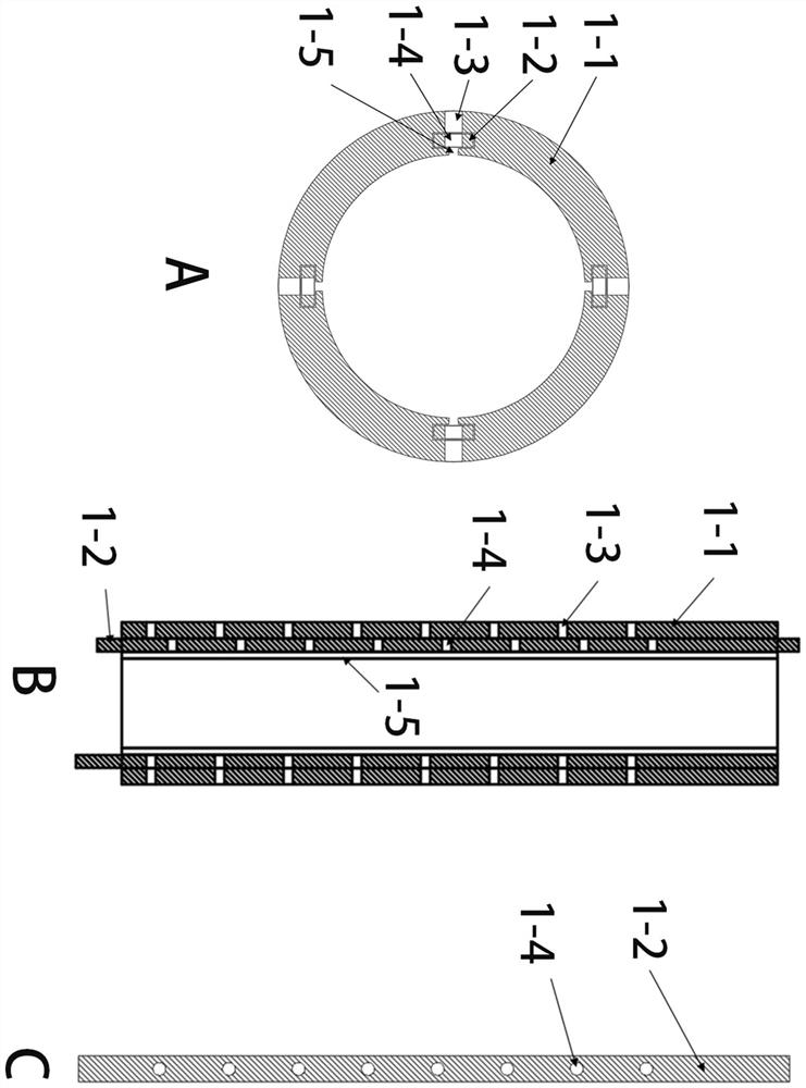
[0015] Referring to the accompanying drawings, a hydraulic damper includes: an outer casing 3, a hydraulic cylinder 1, a piston 2, a one-way valve 4; a switch flap 1-2; a switch flap driving device 1-6; the hydraulic cylinder 1 is arranged in the outer casing 3; the hydraulic cylinder is provided with a piston 2-2 that moves along the axial direction of the hydraulic cylinder; an overflow chamber Q-2 is formed between the outer casing 3 and the inner hydraulic cylinder 1; The hydraulic working pressure chamber Q-1 with variable volume is defined by the inner end of the piston 2-2 and the hydraulic cylinder; the hydraulic cylinder has a hydraulic balance chamber Q-3 with variable volume, the hydraulic pressure The balance chamber Q-3 is defined in the annular space between the outer end of the piston 2-2 and the hydraulic cylinder, the pressure chamber Q-1 and the balance chamber Q-3 are separated by the piston 2-2 in the hydraulic cylinder, and the balance chamber Q -3 is dire...


PUM


Abstract

A hydraulic damper comprises an outer shell, a hydraulic cylinder body, a switch blocking piece, a switch blocking piece driving device, a one-way valve and a piston located in the hydraulic cylinder body, the hydraulic cylinder body is arranged in the outer shell, and an overflow cavity is formed between the outer shell and the hydraulic cylinder body. The piston divides the hydraulic cylinder body into an upper balance cavity and a lower working pressure cavity. A plurality of longitudinal communicating channels are arranged on the hydraulic cylinder body in the circumferential direction at equal intervals. And when the piston is compressed or stretched in the hydraulic cylinder, the equivalent sectional area of the circulation channel in the working pressure cavity is also changed, so that the damping coefficient is changed along with the movement of the piston.

Description

technical field [0001] The invention relates to the technical field of dampers, in particular to a hydraulic damper for shock absorption. Background technique [0002] The general structure of the existing hydraulic damper is: a hollow cylindrical hydraulic cylinder casing, a piston and a piston rod, and the piston can move axially in the hydraulic cylinder casing. A certain amount of hydraulic fluid is contained in the working pressure chamber in the housing. The working chamber is communicated with the overflow chamber through the orifice oil circuit and the special structure valve. [0003] During the compression process of the damper, when the load pushes the piston into the housing, the hydraulic fluid will be forced to enter the overflow chamber simultaneously through the orifice oil circuit and the special structure valve as the volume of the working pressure chamber decreases. [0004] Under normal conditions, when the speed of the piston rod is less than the locki...

Claims


Application Information

Patent Timeline
IPC IPC(8): F16F9/19F16F9/34F16F9/32
CPCF16F9/19F16F9/34F16F9/3235F16F9/3214F16F9/3207
Inventor 龚颖
Owner 龚颖
Learn More