
Self-locking structure and self-locking method of throttling device

A technology of throttling device and self-locking structure, applied in valve devices, devices preventing accidental or unauthorized action, valve details, etc., can solve problems such as hazards, and achieve the effect of easy implementation and simple structure

Pending Publication Date: 2022-07-08
PETROCHINA CO LTD
View PDF0 Cites 0 Cited by
  • Summary
  • Abstract
  • Description
  • Claims
  • Application Information

AI Technical Summary

Problems solved by technology

[0005] The embodiment of the present application provides a self-locking structure and self-locking method of the throttling device, which can solve the problem in the related art that if the slide valve is opened when the upper valve body is opened, it will cause harm

Method used


Image

  • Self-locking structure and self-locking method of throttling device
  • Self-locking structure and self-locking method of throttling device
  • Self-locking structure and self-locking method of throttling device

Examples


Embodiment Construction

[0064] In order to make the objectives, technical solutions and advantages of the present application clearer, the embodiments of the present application will be further described in detail below with reference to the accompanying drawings.

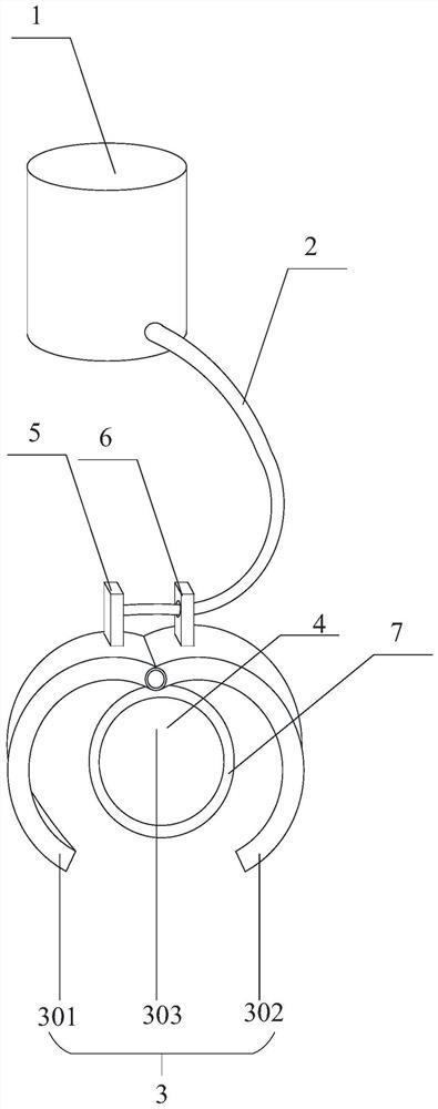
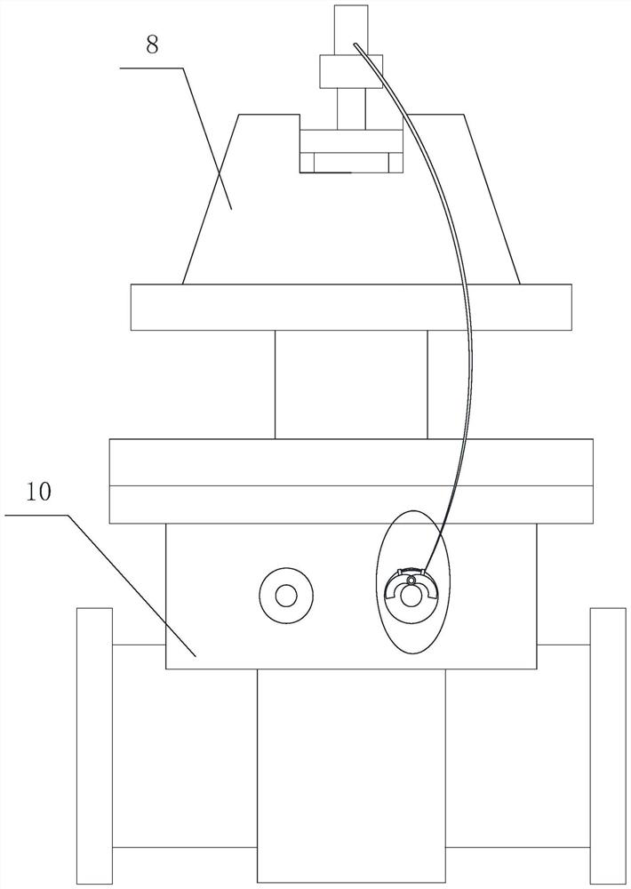
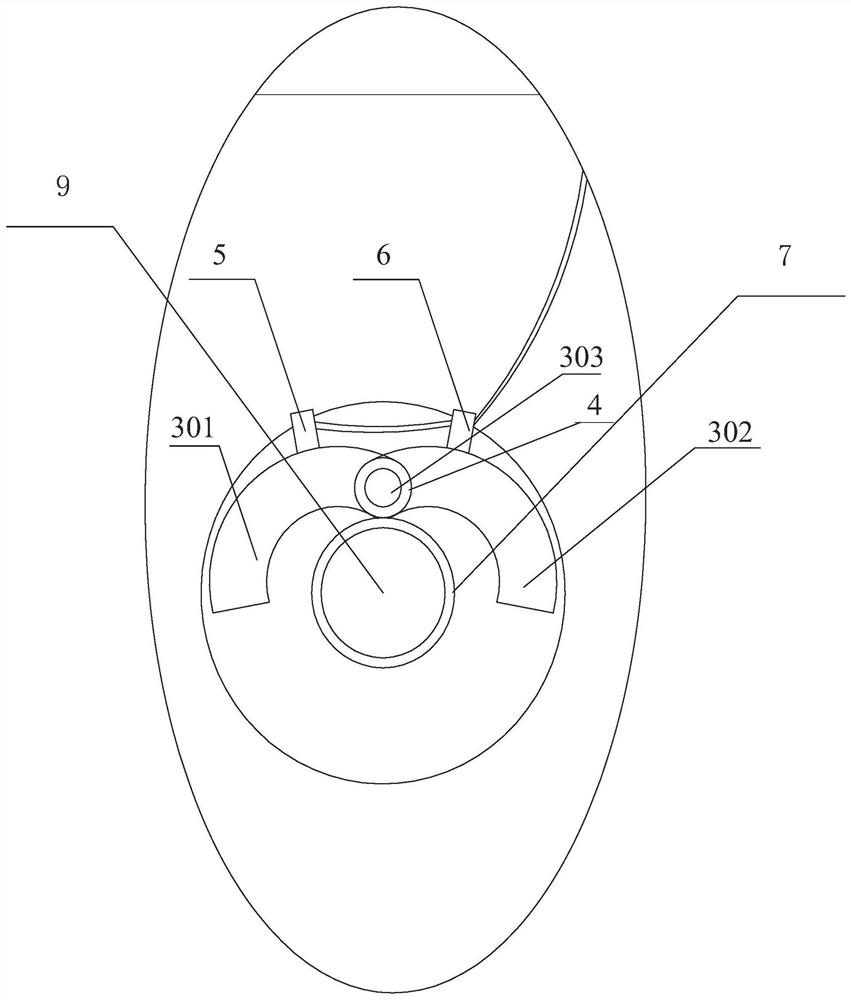
[0065] figure 1 is a schematic structural diagram of a self-locking structure shown according to an exemplary embodiment, figure 2 is a schematic structural diagram of a self-locking structure unfolding according to an exemplary embodiment, image 3 is an enlarged schematic diagram of a self-locking structure unfolded according to an exemplary embodiment, Figure 4 is a schematic structural diagram of a self-locking structure clamping a spool valve drive shaft according to an exemplary embodiment, Figure 5 It is a schematic structural diagram of a self-locking structure clamping a spool valve transmission shaft according to an exemplary embodiment. like figure 1 , figure 2 , image 3 , Figure 4 , Figure 5 As shown, the self-l...


PUM


Abstract

The invention discloses a self-locking structure and a self-locking method of a throttling device, and belongs to the field of oil and gas exploitation. The self-locking structure comprises a valve cover, a pull wire and a clamping device. The pull wire is respectively connected with the valve cover and the clamping device; the clamping device is used for clamping the slide valve rotating shaft; when the valve cover is arranged on the upper valve body of the throttling device in a sleeving mode, the pull wire drives the clamping device to be opened through pull force, and the sliding valve rotating shaft is loosened. When the valve cover is separated from the upper valve body of the throttling device, the pull wire loses pull force, the sliding valve rotating shaft is clamped by the clamping device, the sliding valve cannot be operated at the moment, the situation that the sliding valve is opened when the upper valve body is opened is prevented, the situation that the upper valve body rushes out of the throttling piece and natural gas to cause harm is avoided, and in addition, the safety of the throttling device is improved. The self-locking structure is simple, the throttling device does not need to be improved, and the self-locking structure is easy to implement.

Description

technical field [0001] The application relates to the field of oil and gas exploitation, and in particular, to a self-locking structure and a self-locking method of a throttling device. Background technique [0002] Oil or gas is an essential material in people's lives, and the transportation of oil and gas has become an essential process. In the process of conveying oil or natural gas, the throttling device can be used to measure the flow in the conveying pipeline, so that the conveying speed can be monitored in real time. [0003] The throttling device includes a throttling piece, a slide valve, an upper valve body and a lower valve body. When the throttling device needs to be checked and cleaned, the slide valve needs to be closed to separate the lower valve body and the upper valve body. The fluid in the lower valve body can flow normally, and the fluid in the lower valve body will not be ejected from the upper valve body, and after closing the slide valve, the throttli...

Claims


Application Information

Patent Timeline
Patent Type & Authority Applications(China)
IPC IPC(8): F16K35/06
CPCF16K35/06Y02B30/70
Inventor 张开炳谢宗宝张永梅王晓刚王小丹杨红程兴洁刘长林胡明张啟超
Owner PETROCHINA CO LTD
Learn More