High-low temperature current-carrying fatigue test system for air-conditioning duct of airplane

An air-conditioning air duct and fatigue testing technology, which is applied in the field of simulation test, can solve problems such as difficulty in air duct maintenance and repair, pipeline leakage, thermal insulation and sealing that affect the temperature adjustment efficiency of air-conditioning units, and achieve the effect of saving maintenance and upgrading costs

Active Publication Date: 2022-07-08
HUNAN UNIV OF ARTS & SCI
View PDF7 Cites 0 Cited by
  • Summary
  • Abstract
  • Description
  • Claims
  • Application Information

AI Technical Summary

Problems solved by technology

[0003] Second, due to the tight structure of the engine room, the layout of the air duct itself makes it difficult to carry out routine maintenance and repairs, so the design, manufacture and installation of the air duct need to have high reliability;
[0004] Third, as passengers have higher requirements for the air atmosphere in the cabin, the uniformity of air supply from the air-conditioning duct, the controllability of the wind speed, and the uniformity of the temperature in the cabin all directly affect the comfort of passengers; Insulation and sealing in high and low temperature environments will also directly affect the temperature regulation efficiency of the air conditioning unit
[0005] Further, when the aircraft is flying, the difference between the temperature outside the cabin and the temperature inside the cabin can reach tens of degrees; and in the normal working process and during the flight up and down, the temperature inside and outside the pipe of the air duct is also constantly changing; thus it is also possible All kinds of air path problems are generated; common ones are pressure loss caused by pipeline leakage and low air conditioning efficiency; or the strength of the pipeline is reduced due to mechanical fatigue, which eventually leads to abnormal deformation and vibration; further, due to the heat that may be generated at the joints of various components Accumulation, frequent vibration and other reasons are prone to blockage, loosening, leakage and other phenomena after long-term use; therefore, the thermal fatigue and vibration fatigue of the air-conditioning air circuit need to be fully verified before implementation to ensure the safety of the aircraft air-conditioning pipeline sex

Method used


Image

  • High-low temperature current-carrying fatigue test system for air-conditioning duct of airplane
  • High-low temperature current-carrying fatigue test system for air-conditioning duct of airplane
  • High-low temperature current-carrying fatigue test system for air-conditioning duct of airplane

Examples


Embodiment 1

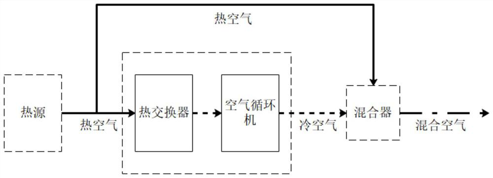
[0054] as attached figure 2 As shown, the schematic diagram of the conventional aircraft air conditioning system is described; when the aircraft engine is working, the outside air is sucked in, and after the action of the internal compressor, the pressure and temperature will rise significantly; the engine, auxiliary power components, or compressor are all It can be used as a heat source to generate hot air; high-pressure hot air with a temperature of 150°C to 200°C and a pressure of 30psi-50psi is drawn from the heat source; when the air conditioner is started, the temperature control computer controls the flow control valve to open, so that the high-pressure hot air enters the air conditioner components, The core components of the module are the heat exchanger and the air circulation machine. When the high-pressure hot air passes through the heat exchanger, a part of the heat is taken away by the external cold air, and the temperature decreases significantly, but the pressur...

Embodiment 2

[0087] This embodiment should be understood as including at least all the features of any one of the foregoing embodiments, and further improved on the basis thereof;

[0088] as attached Figure 5 shown, is an embodiment of the test segment;

[0089] Optionally, the outer surface of the test section 200 adopts a metal panel as the outer panel to provide a solid outer structure surface; Condensed water generated at low temperature of test section 200;

[0090] The inner surface material of the test section 200 is polyoxymethylene resin (POM), which is formed into a cube by direct molding and is embedded in the outer panel; POM is a linear type without side chains, high density and high crystallinity. Polymers, of which polyoxymethylene materials are preferably used; POM materials have high stiffness, good elasticity, and good wear resistance and wear resistance; their mechanical properties are excellent, with a specific strength of up to 50.5MPa and a specific stiffness of u...

Embodiment 3

[0099] This embodiment should be understood as including at least all the features of any one of the foregoing embodiments, and further improved on the basis thereof;

[0100] In the test section 200, the vibration device is also included; Figure 7 , is a schematic diagram of the temperature control device; wherein, the vibration device includes a horizontal vibrator and a vertical vibrator; the horizontal vibrator is in contact with the horizontal side of the pipe fittings in the test section 200 for generating Vibration in the horizontal direction; the vertical vibrator is arranged below the pipe fitting and is in contact with the pipe fitting to generate vertical vibration;

[0101] Preferably, the horizontal vibrator and the vertical vibrator comprise a casing and a vibrator part;

[0102] The casing includes an outer casing 708 and an inner casing 701; the inner casing 701 is a frame body with an open structure at the upper and lower parts; the inner casing 701 is arran...


PUM


Abstract

The invention relates to a high-low temperature current-carrying fatigue test system for an air-conditioning duct for an airplane, and the system comprises a simulation wind path which is used as a test wind path of the test system through simulating a real air-conditioning wind path of the airplane; the simulation unit is used for simulating various environment working conditions of the aircraft air conditioning system in flight; the detection unit comprises a plurality of sensor devices and is used for detecting working condition data and environment data of each link in the simulation wind path; wherein the simulation wind path comprises a plurality of pipelines and pipeline accessories which are scaled according to the equal proportion of a real air conditioner wind path, the simulation unit comprises a plurality of test sections and wraps the multiple sections of wind path pipelines, and the external temperature and the vibration environment of the pipelines in the working process are simulated, so that the simulation wind path can be simulated. And performing a fatigue test on the simulated wind path and analyzing according to fatigue test data.

Description

technical field [0001] The invention relates to the technical field of simulation experiments. Specifically, it relates to a high and low temperature current-carrying fatigue test system for an air-conditioning air duct used in an aircraft. Background technique [0002] With the improvement of people's living standards, aircrafts play an important role in travel, transportation and other applications as large-scale fast transportation; and as people's requirements for aircraft riding experience increase, the comfort in the cabin is getting higher and higher. requirements. In the current related research fields, one is that the air-conditioning system of the aircraft has been in a long-term working state, and the inside of the air duct is in a current-carrying environment with a great difference between high and low temperature for a long time. Various materials of the air duct will have very severe temperature fatigue. question; [0003] Second, due to the compact structu...

Claims


Application Information

Patent Timeline
Patent Type & Authority Applications(China)
IPC IPC(8): G01M13/00
CPCG01M13/00Y02T50/50
Inventor 屠毅尹亮郑秋云曾宇姜茜陈宣任
Owner HUNAN UNIV OF ARTS & SCI
Why Eureka
Try Eureka