Particle counting method, device and system suitable for imaging flow cytometry

A flow cytometer and particle counting technology, which is applied in the field of flow cytometry, can solve the problems of particle omission and inaccuracy, and achieve the effect of simple counting method, strong portability and high reliability

Pending Publication Date: 2022-07-08
ZHEJIANG UNIV
View PDF0 Cites 0 Cited by
  • Summary
  • Abstract
  • Description
  • Claims
  • Application Information

AI Technical Summary

Problems solved by technology

[0006] The purpose of the embodiment of the present application is to provide a particle counting method, device, and system suitable for imaging flow cytometers, so as to solve the technology of inaccurate counting caused by missing particles in the counting process of imaging flow cytometers existing in the related art question

Method used


Image

  • Particle counting method, device and system suitable for imaging flow cytometry
  • Particle counting method, device and system suitable for imaging flow cytometry
  • Particle counting method, device and system suitable for imaging flow cytometry

Examples


Embodiment Construction

[0065] Exemplary embodiments will be described in detail herein, examples of which are illustrated in the accompanying drawings. Where the following description refers to the drawings, the same numerals in different drawings refer to the same or similar elements unless otherwise indicated. The implementations described in the illustrative examples below are not intended to represent all implementations consistent with this application. Rather, they are merely examples of apparatus and methods consistent with some aspects of the present application as recited in the appended claims.

[0066] The terminology used in this application is for the purpose of describing particular embodiments only and is not intended to limit the application. As used in this application and the appended claims, the singular forms "a," "the," and "the" are intended to include the plural forms as well, unless the context clearly dictates otherwise. It will also be understood that the term "and / or" as...


PUM


Abstract

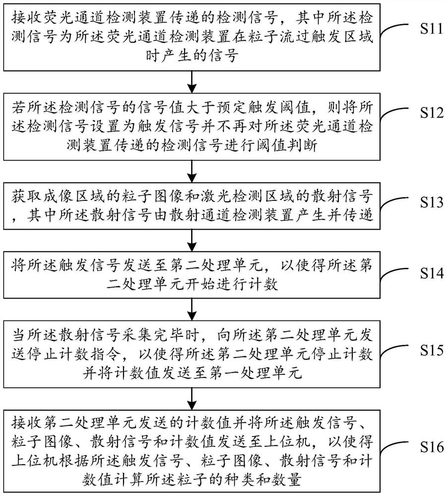
The invention discloses a particle counting method, device and system suitable for an imaging flow cytometer. The method comprises the following steps: receiving a detection signal transmitted by a fluorescence channel detection device; if the signal value of the detection signal is greater than a preset trigger threshold value, setting the detection signal as a trigger signal and not performing threshold value judgment on the detection signal transmitted by the fluorescence channel detection device; obtaining a particle image of the imaging area and a scattering signal of the laser detection area; sending the trigger signal to a second processing unit to enable the second processing unit to start counting; when the scattered signals are collected, a counting stopping instruction is sent to the second processing unit, so that the second processing unit stops counting and sends a counting value to the first processing unit; and receiving the count value sent by the second processing unit, and sending the trigger signal, the particle image, the scattering signal and the count value to an upper computer, so that the upper computer calculates the type and the number of the particles.

Description

technical field [0001] The present application relates to the technical field of flow cytometry, and in particular, to a particle counting method, device, and system suitable for an imaging flow cytometer. Background technique [0002] Flow cytometry technology is a widely used technology. Its working principle is: prepare the cells of the sample to be tested into a single cell suspension, use the autofluorescence of the cells, or label the cells with specific fluorescent probes, Under the constraint of a certain flow rate and sheath fluid, the cell fluid column passes through the laser detector in a single arrangement. The cell liquid column intersects vertically with the excitation light incident in the detector, and by measuring its scattered light (including forward-phase scattered light and side-phase scattered light), cell autofluorescence, dye-stained fluorescence, and probe-labeled fluorescence, etc. Characteristic target organisms are distinguished from background ...

Claims


Application Information

Patent Timeline
IPC IPC(8): G01N15/14
CPCG01N15/14G01N15/1434G01N2015/144G01N2015/1486G01N15/1433
Inventor 王杭州郭侃黄顶棚黄慧宋宏陈鹰
Owner ZHEJIANG UNIV
Why Eureka
Try Eureka