
Battery pack thermal runaway detection method and device

A detection method and thermal runaway technology, applied in battery temperature control, secondary batteries, circuits, etc., can solve the problem of inability to handle temperature, voltage and current, inability to complete the installation of thermal runaway components, and inability to realize the detection of thermal runaway of battery packs, etc. question

Pending Publication Date: 2022-07-08
WANXIANG 123 CO LTD
View PDF0 Cites 0 Cited by
  • Summary
  • Abstract
  • Description
  • Claims
  • Application Information

AI Technical Summary

Problems solved by technology

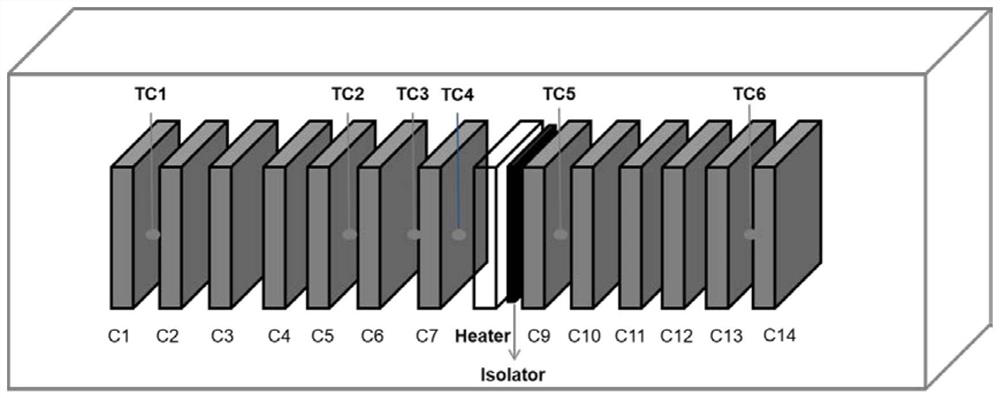
[0002] At present, the existing battery packs are relatively compact in structure, usually in the form of 1P14S combination. Due to the tight connection between different cells, it is very inconvenient to test the thermal runaway inside the cells. When performing a thermal runaway test on a 1P14S structure battery pack, it is necessary to remove one battery cell of the battery pack, otherwise the installation of the thermal runaway component will not be completed
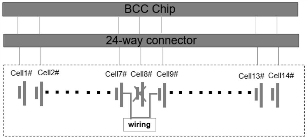
However, if one of the cells in the battery pack is removed, the electrical circuit inside the cell will be disconnected, causing the BMS chip of the battery pack to report an undervoltage fault, unable to process signals such as temperature, voltage, and current, and thus unable to achieve battery pack heating. runaway detection
Moreover, the detection method for thermal runaway in the prior art is only obtained by judging a single condition, which makes the detection of thermal runaway not accurate enough

Method used


Image

  • Battery pack thermal runaway detection method and device
  • Battery pack thermal runaway detection method and device
  • Battery pack thermal runaway detection method and device

Examples


Embodiment Construction

[0029] The following description serves to disclose the invention to enable those skilled in the art to practice the invention. The preferred embodiments described below are given by way of example only, and other obvious modifications will occur to those skilled in the art. The basic principles of the invention defined in the following description may be applied to other embodiments, variations, improvements, equivalents, and other technical solutions without departing from the spirit and scope of the invention.

[0030] It should be understood that the term "a" should be understood as "at least one" or "one or more", that is, in one embodiment, the number of an element may be one, while in another embodiment, the number of the element may be one. The number may be plural, and the term "one" should not be understood as a limitation on the number.

[0031] Please refer to Figure 1-3 , The present invention discloses a battery pack thermal runaway detection method and device...


PUM


Abstract

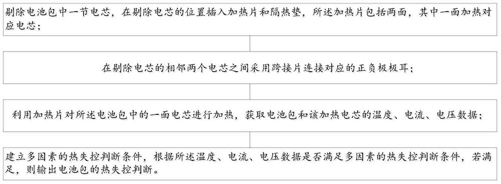
The invention discloses a battery pack thermal runaway detection method and device, and the method comprises the steps: removing a battery cell in a battery pack, inserting a heating sheet and a heat insulation pad at the position where the battery cell is removed, the heating sheet comprises two surfaces, and one surface heats the corresponding battery cell; connecting the corresponding positive and negative tabs between the two adjacent battery cells without the battery cells by adopting a bridging piece; heating a battery cell on one side in the battery pack by using a heating sheet to obtain temperature, current and voltage data of the battery pack and the heated battery cell; and establishing multi-factor thermal runaway judgment conditions, and outputting thermal runaway judgment of the battery pack according to whether the temperature, the current and the voltage data meet the multi-factor thermal runaway judgment conditions or not if the temperature, the current and the voltage data meet the multi-factor thermal runaway judgment conditions. A heating piece, a heat insulation pad and a bridging piece are additionally arranged between two adjacent battery cells in the middle, and the bridging piece is used for connecting a terminal between the two adjacent battery cells, so that the situation that the BMS cannot detect related signals due to open circuit is avoided.

Description

technical field [0001] The invention relates to the technical field of thermal runaway detection, in particular to a battery pack thermal runaway detection method and system. Background technique [0002] At present, the structure of the existing battery pack is relatively compact, usually in the form of a combination of 1P14S. Due to the tight connection between different cells, it is very inconvenient for the thermal runaway test inside the cell. When the thermal runaway test of the 1P14S structure battery pack is carried out, one cell of the battery pack needs to be removed, otherwise the installation of the thermal runaway component will not be completed. However, if one cell of the battery pack is removed, the electrical circuit inside the cell will be disconnected, which will cause the BMS chip of the battery pack to report an undervoltage fault, unable to process signals such as temperature, voltage, and current, thus failing to achieve battery pack heating. Runaway ...

Claims


Application Information

Patent Timeline
IPC IPC(8): H01M10/48H01M10/613H01M10/63
CPCH01M10/613H01M10/63H01M10/486Y02E60/10
Inventor 张磊王换换徐松
Owner WANXIANG 123 CO LTD
Learn More