Joint debugging method and device for monitoring equipment
A technology of monitoring equipment and joint debugging, applied in the direction of comprehensive factory control, TV, CCTV system, etc., can solve the problems of single technical interface matching, affecting the efficiency of joint debugging of monitoring equipment, labor and time cost, etc., to improve flexibility , Improve the efficiency of joint debugging, improve the effect of processing speed
- Summary
- Abstract
- Description
- Claims
- Application Information
AI Technical Summary
Problems solved by technology
Method used
Image
Examples
Embodiment 1
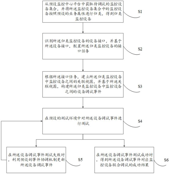
[0056] see figure 1 As shown, it is a schematic flowchart of a joint debugging method for monitoring equipment provided by an embodiment of the present invention. in, figure 1 The joint debugging method of monitoring equipment described in includes:
[0057] S1. Acquire a monitoring device set to be debugged from a preset monitoring center platform, and classify the monitoring devices in the monitoring device set according to preset service attributes to obtain a classified monitoring device.
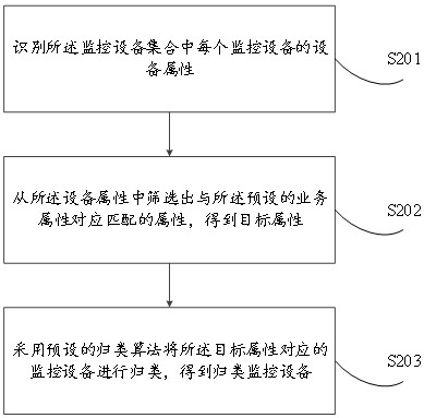
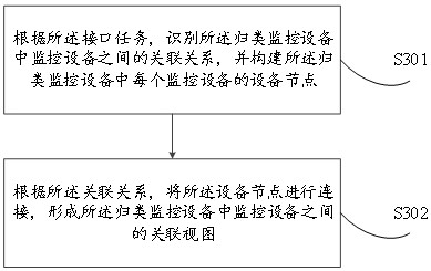
[0058] In the embodiment of the present invention, the preset monitoring center platform is constructed based on different business scenarios. For example, in a traffic supervision scenario, the monitoring center platform may be a traffic command center platform, and in a community security management scenario, the monitoring center platform The platform may be a community security monitoring center platform, and the set of monitoring equipment to be debugged refers to a set of joint ...
Embodiment 2
[0098] like Figure 4 As shown, it is a functional block diagram of the joint debugging device of the monitoring equipment of the present invention.
[0099] The joint debugging device 400 of the monitoring equipment according to the present invention can be installed in the electronic equipment. According to the realized functions, the joint debugging device of the monitoring device may include a monitoring device classification module 401, an interface task configuration module 402, a debugging event building module 403, a debugging event testing module 404, a debugging event updating module 405, and a debugging result generating module 406. The modules in the present invention can also be called units, which refer to a series of computer program segments that can be executed by the electronic device processor and can perform fixed functions, and are stored in the memory of the electronic device.
[0100] In this embodiment of the present invention, the functions of each m...
Embodiment 3
[0109] like Figure 5 As shown, it is a schematic structural diagram of an electronic device implementing the joint debugging method for monitoring devices according to the present invention.
[0110] The electronic device may include a processor 50, a memory 51, a communication bus 52, and a communication interface 53, and may also include a computer program stored in the memory 51 and executable on the processor 50, such as a combination of monitoring devices. Debugger.
[0111] The processor 50 may be composed of integrated circuits in some embodiments, for example, may be composed of a single packaged integrated circuit, or may be composed of multiple integrated circuits packaged with the same function or different functions, including one or A combination of multiple central processing units (CPUs), microprocessors, digital processing chips, graphics processors, and various control chips. The processor 50 is the control core (ControlUnit) of the electronic device, and u...
PUM
 Abstract
Description
Claims
Application Information
 - R&D Engineer
- R&D Manager
- IP Professional
- Industry Leading Data Capabilities
- Powerful AI technology
- Patent DNA Extraction
Browse by: Latest US Patents, China's latest patents, Technical Efficacy Thesaurus, Application Domain, Technology Topic, Popular Technical Reports.
© 2024 PatSnap. All rights reserved.Legal|Privacy policy|Modern Slavery Act Transparency Statement|Sitemap|About US| Contact US: help@patsnap.com


