Heat dissipation device and electronic equipment

A heat dissipation device and technology, applied in the direction of cooling/ventilation/heating transformation, etc., can solve problems such as unfavorable liquid replenishment, inability to form a heat transfer cycle, and easy to burn out.

Active Publication Date: 2022-07-08
HUAWEI TECH CO LTD
View PDF6 Cites 1 Cited by
  • Summary
  • Abstract
  • Description
  • Claims
  • Application Information

AI Technical Summary

Problems solved by technology

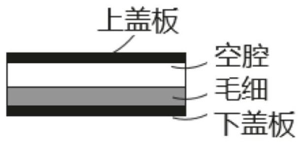
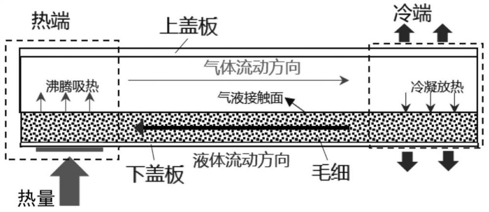
[0004] In the existing vapor chamber, the steam flow direction is opposite to the liquid flow direction in the liquid-absorbing core structure, and the steam flowing in the opposite direction may carry condensed liquid droplets, so that the condensed liquid droplets stay in the condensation area, which is not conducive to returning liquid to the evaporation area For rehydration, it is prone to dry out and cannot form a reliable heat transfer cycle

Method used


Image

  • Heat dissipation device and electronic equipment
  • Heat dissipation device and electronic equipment
  • Heat dissipation device and electronic equipment

Examples


Embodiment Construction

[0056] The technical solutions in the embodiments of the present application will be described below with reference to the accompanying drawings in the embodiments of the present application.

[0057] In the description of this application, the terms "center", "upper", "lower", "front", "rear", "left", "right", "vertical", "horizontal", "top", " The orientation or positional relationship indicated by "bottom", "inside", "outside", etc. is based on the orientation or positional relationship shown in the drawings, and is only for the convenience of describing the present application and simplifying the description, rather than indicating or implying the indicated device or Elements must have a particular orientation, be constructed and operate in a particular orientation, and therefore are not to be construed as limitations of the present application.

[0058] In the description of this application, it should be noted that, unless otherwise expressly specified and limited, the t...


PUM


Abstract

The embodiment of the invention provides a heat dissipation device and electronic equipment. The heat dissipation device comprises a shell and a fluid working medium, the shell internally comprises an evaporation area and a condensation area, and the evaporation area is arranged at the heating device, so that the fluid working medium at the evaporation area forms steam and flows to the condensation area; the wick structure is arranged in the shell, a steam flowing channel is formed in the shell, the wick structure comprises a first flow guide wick, a second flow guide wick and a backflow wick, and the first flow guide wick is located in the evaporation area; the first end of the second diversion wick is suspended and located in the condensation area or extends to the evaporation area, and the second end is located in the condensation area; the backflow wick is connected with the second end of the second flow guide wick and the first flow guide wick; the first end of the second flow guide wick is close to the evaporation area relative to the second end of the second flow guide wick along the steam flowing channel. The steam and liquid flow in the same direction, the liquid is prevented from being retained in the condensation area due to the fact that the steam flowing reversely carries the liquid, the liquid can return to the evaporation area easily, drying-out is prevented, and reliability is improved.

Description

technical field [0001] The present application relates to the technical field of terminals, and in particular, to a heat sink and an electronic device. Background technique [0002] In terminal devices such as mobile phones, tablets, notebooks, PCs, large screens, etc., the heating power of electronic devices gradually increases with product iterations. However, the overall size and thickness of the devices are developing in a compact and small direction, resulting in heat accumulation in the device. The inside cannot be dissipated in time, so that the temperature rises, which not only affects the user experience, but also may cause high temperature damage to the device. Therefore, the industry urgently needs various efficient heat dissipation solutions to solve the problem of heat dissipation of terminal equipment. [0003] A vapor chamber (VC) is a vacuum cavity with a micro-nano liquid-absorbing core structure inside and injected with a fluid working medium. It is widely...

Claims


Application Information

Patent Timeline
Patent Type & Authority Applications(China)
IPC IPC(8): H05K7/20
CPCH05K7/20309H05K7/20318H05K7/20327
Inventor 骆洋刘用鹿陈丘靳林芳
Owner HUAWEI TECH CO LTD
Why Eureka
Try Eureka