Newborn transfer incubator for intensive care unit
A technology for intensive care units and newborns, applied in the direction of baby incubators, medical transportation, transportation and packaging, etc., to achieve the effect of height adjustment, ingenious conception, and improved safety
- Summary
- Abstract
- Description
- Claims
- Application Information
AI Technical Summary
Problems solved by technology
Method used
Image
Examples
Embodiment 1
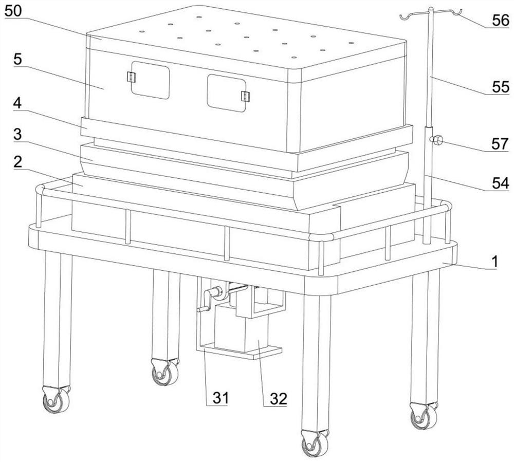
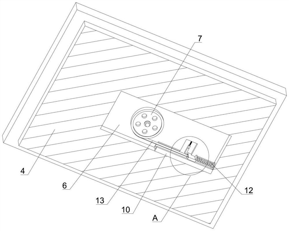
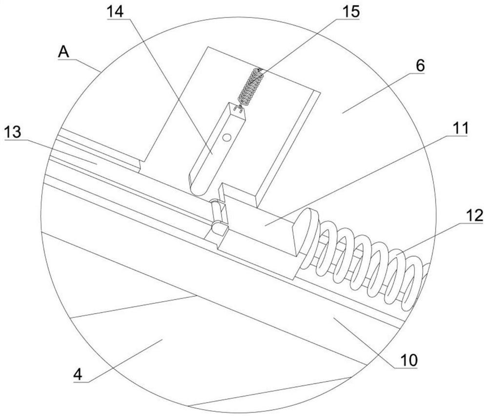
[0041] Example one, by Figure 1-5Given, the present invention includes a vehicle body 1, in order to achieve the purpose of buffering the newborn, the bottom of the vehicle body 1 is fixedly connected with a lifting mechanism, the top of the lifting mechanism is fixedly connected with a base 2, and the top of the base 2 is Arc surface, the interior of the base 2 is provided with a rotating seat 3, the bottom of the rotating base 3 is a convex surface, the arc surface at the top of the base 2 and the convex surface at the bottom of the rotating base 3 have the same radian, and the front and rear albums inside the base 2 are symmetrically opened. An arc-shaped groove, the front and rear sides of the rotating seat 3 are fixedly connected with a bayonet that can slide along the corresponding arc-shaped groove, the top of the rotating seat 3 is slidably connected with a placing seat 4, and the interior of the placing seat 4 is slidably connected There is a transfer box 5, in order...
Embodiment 2
[0045] Embodiment 2, on the basis of Embodiment 1, by Figure 6-10 Given, in order to achieve the purpose of fixedly protecting the body and head of the newborn, a second driven gear 16 is rotatably connected inside the transfer box 5, and a first driven gear 16 is fixedly connected to the bottom end of the second driven gear 16. A bevel gear, the bottom end of the second driven gear 16 is meshed with a driving shaft 17, the front end of the driving shaft 17 is fixedly connected with a second bevel gear that meshes with the first bevel gear, and the rear end of the driving shaft 17 is fixed A hand wheel is connected, the inside of the transfer box 5 is slidably connected with two second racks 18 that mesh with the second driven gear 16, and the top of each second rack 18 is fixedly connected with a The baffles 19, one side of each baffle 19 is fixedly connected with a soft pad, the bottom end of the second driven gear 16 is engaged with a first driven shaft 20, the rear of the...
Embodiment 3
[0048] Embodiment 3, on the basis of Embodiment 1, by Figure 11 and Figure 12 Given, in order to achieve the purpose of shock absorption, two sliding rods 26 are fixedly connected to the inside of the rotating base 3, and a first shock-absorbing spring 27 is fixedly connected to the middle of the two sliding rods 26. Both ends of the first shock-absorbing spring 27 are fixedly connected with a connecting block 28 that can slide back and forth along the corresponding sliding rod 26, and a connecting rod 29 is rotatably connected between each of the connecting blocks 28 and the placing seat 4, A plurality of second shock-absorbing springs 30 are fixedly connected between the placing seat 4 and the rotating seat 3 , and a limit rod 59 is arranged inside each of the second shock-absorbing springs 30 , and each limit rod 59 The top of each limit rod 59 is fixedly connected to the bottom of the placing seat 4, and the bottom of each limit rod 59 is provided with a clamping table;...
PUM
 Abstract
Description
Claims
Application Information
 - R&D
- Intellectual Property
- Life Sciences
- Materials
- Tech Scout
- Unparalleled Data Quality
- Higher Quality Content
- 60% Fewer Hallucinations
Browse by: Latest US Patents, China's latest patents, Technical Efficacy Thesaurus, Application Domain, Technology Topic, Popular Technical Reports.
© 2025 PatSnap. All rights reserved.Legal|Privacy policy|Modern Slavery Act Transparency Statement|Sitemap|About US| Contact US: help@patsnap.com


