Convenient-to-use oil changing device for hydraulic control system of wind turbine generator
A technology for hydraulic control systems and wind turbines, applied in fluid pressure actuation devices, fluid pressure actuation system components, wind power generation, etc., can solve problems such as troublesome, many tools, and increased difficulty of high-altitude operations, so as to improve safety, The effect of less auxiliary tools and simple structure
- Summary
- Abstract
- Description
- Claims
- Application Information
AI Technical Summary
Problems solved by technology
Method used
Image
Examples
Embodiment example 1
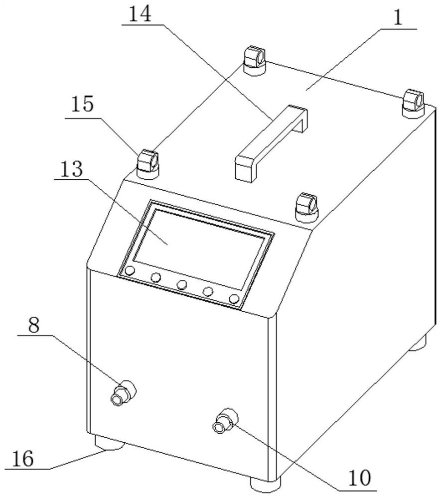
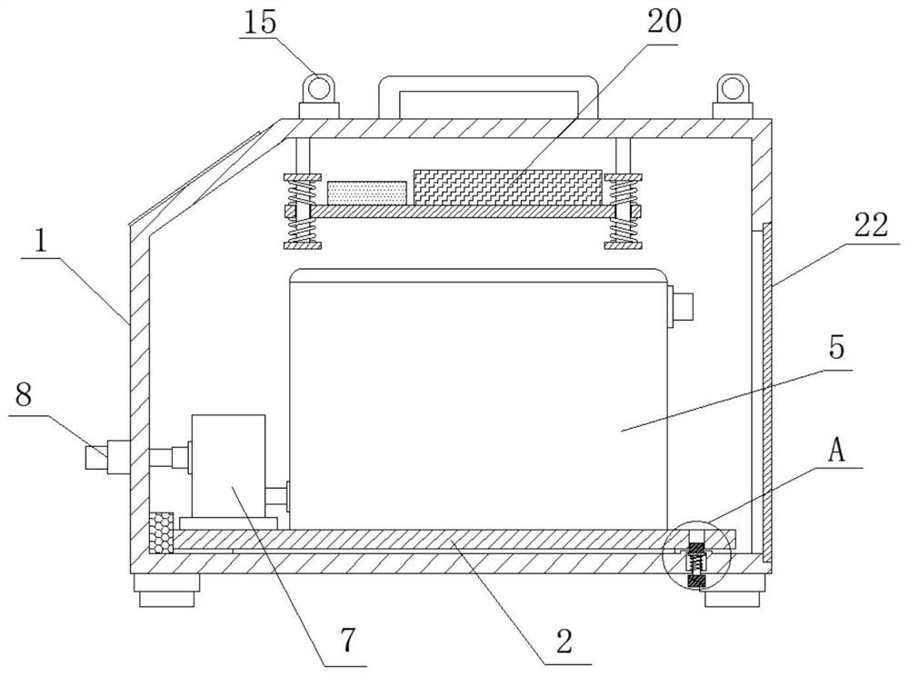
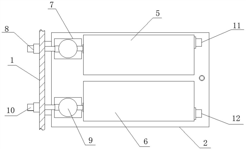
[0030] like Figure 1-4 As shown, the present invention provides a technical solution: an easy-to-use oil changer for a hydraulic control system of a wind turbine, comprising a body 1, a mounting plate 2 is arranged inside the body 1, and an oil storage is fixedly installed on the mounting plate 2 The barrel 5, the left port of the oil storage barrel 5 is connected with the first delivery pump 7, the left port of the first delivery pump 7 is connected with the first one-way valve 8, the first one-way valve 8 is fixedly installed on the front of the body 1, and the installation A waste oil drum 6 is fixedly installed on the upper surface of the plate 2, the left port of the waste oil drum 6 is connected with a second delivery pump 9, and the left port of the second delivery pump 9 is connected with a second one-way valve 10, the second one-way valve 10 is fixedly installed on the front of the body 1, the front of the body 1 is provided with a control panel 13, the upper surface...
Embodiment example 2
[0035] like Figure 1-5 As shown, on the basis of implementation case 1, the present invention provides a technical solution: the inside of the body 1 is provided with a protection mechanism 3, the protection mechanism 3 includes a connecting rod 31, and the connecting rod 31 is fixedly installed inside the body 1, which is a connection The rod body of the rod 31 is sleeved with a first buffer spring 33, the upper surface of the placing plate 19 is provided with a through hole 34, the connecting rod 31 penetrates the interior of the through hole 34, and the lower end of the rod body of the connecting rod 31 is sleeved with a second buffer spring 35 The arrangement of the first buffer spring 33 and the second buffer spring 35 can protect the controller 21 and the battery 20 on the placing plate 19 and reduce the damage to the controller 21 and the battery 20 due to collision.
[0036] A first limit plate 32 is fixedly installed on the rod body of the connecting rod 31 , the upp...
Embodiment example 3
[0038] like Figure 1-6 As shown, on the basis of implementation case 1 and implementation case 2, the present invention provides a technical solution: a positioning mechanism 4 is provided inside the body 1, and the positioning mechanism 4 includes a positioning hole 41 and a spring groove 44, and the positioning hole 41 is opened in the On the right end of the upper surface of the mounting plate 2, a spring groove 44 is opened inside the bottom wall of the body 1, a pull rod 45 is arranged inside the spring groove 44, a positioning block 42 is fixedly installed on the upper end of the pull rod 45, and the upper end of the positioning block 42 is inserted in the positioning Inside the hole 41 , the positioning hole 41 and the positioning block 42 can play a role in positioning the mounting plate 2 .
[0039] The rod body of the pull rod 45 is sleeved with a return spring 43, the upper end of the return spring 43 abuts on the bottom of the positioning block 42, and the lower e...
PUM
 Abstract
Description
Claims
Application Information
 - R&D
- Intellectual Property
- Life Sciences
- Materials
- Tech Scout
- Unparalleled Data Quality
- Higher Quality Content
- 60% Fewer Hallucinations
Browse by: Latest US Patents, China's latest patents, Technical Efficacy Thesaurus, Application Domain, Technology Topic, Popular Technical Reports.
© 2025 PatSnap. All rights reserved.Legal|Privacy policy|Modern Slavery Act Transparency Statement|Sitemap|About US| Contact US: help@patsnap.com


