
Pile-up valve capable of being proportionally adjusted

A proportional adjustment and integrated valve technology, applied in the field of integrated valves, can solve problems such as high complexity of control loops, complex flow channel layout, and high manufacturing costs, and achieve the effects of improving social value, reducing the number of pipelines, and simplifying processing

Pending Publication Date: 2022-07-12
CHENGDU WANYOU FILTER
View PDF0 Cites 0 Cited by
  • Summary
  • Abstract
  • Description
  • Claims
  • Application Information

AI Technical Summary

Problems solved by technology

[0003] At present, the thermal management control system of new energy vehicles is becoming more and more complex. In order to realize various control and operation modes of the whole vehicle, the fluid circuit will involve multiple reversing valves and multiple driving mechanisms that control the flow direction of the fluid, and the layout of the flow channels is complicated.
In order to realize the precise distribution of the cooling flow of the passenger compartment and the battery pack, the thermal management control system needs to realize the proportional adjustment of the loop flow, so the thermal management system also needs to add a proportional valve, which will undoubtedly make the entire control loop more complex and the manufacturing cost will also increase. higher

Method used


Image

  • Pile-up valve capable of being proportionally adjusted
  • Pile-up valve capable of being proportionally adjusted
  • Pile-up valve capable of being proportionally adjusted

Examples


Embodiment Construction

[0028] In order to make the purposes, technical solutions and advantages of the embodiments of the present invention clearer, the technical solutions in the embodiments will be clearly and completely described below with reference to the drawings in the embodiments of the present invention, and the following embodiments are used to illustrate the present invention , but are not intended to limit the scope of the present invention.

[0029] In the description of the present invention, it should be noted that the terms "upper", "lower", "front", "rear", "left", "right", "vertical", "inner", "outer", etc. The indicated orientation or positional relationship is based on the orientation or positional relationship shown in the accompanying drawings, which is only for the convenience of describing the present invention and simplifying the description, rather than indicating or implying that the indicated device or element must have a specific orientation or a specific orientation. co...


PUM


Abstract

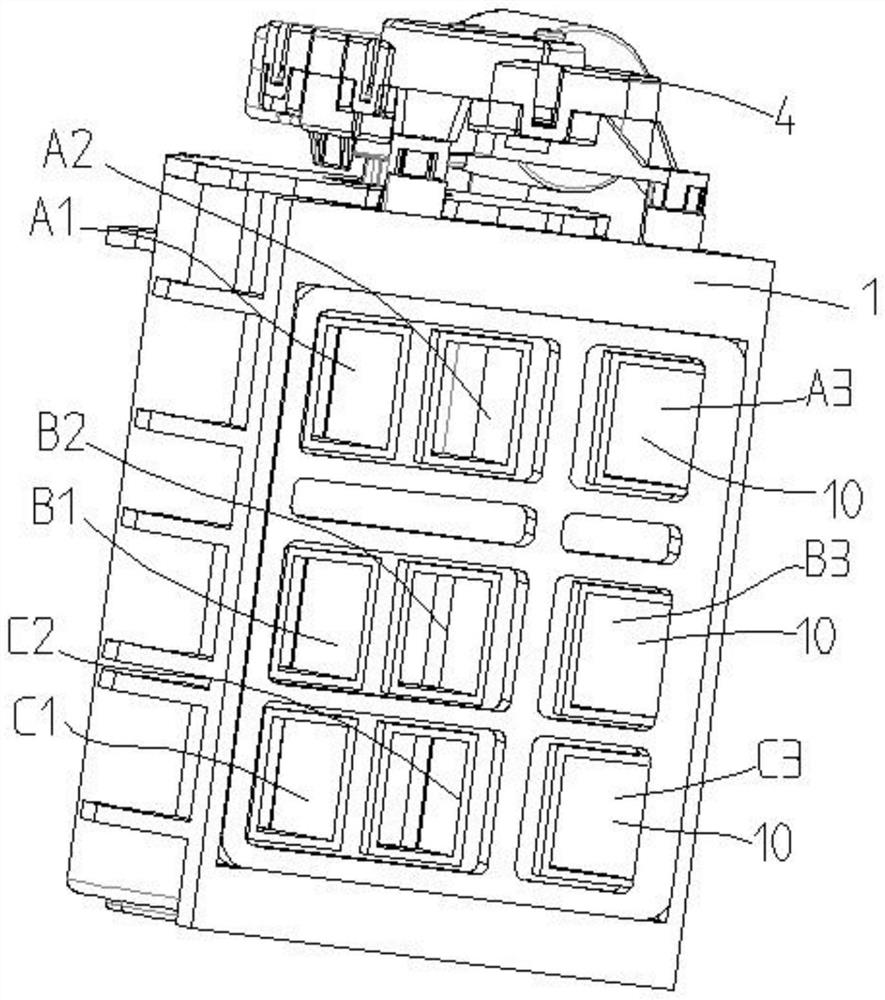
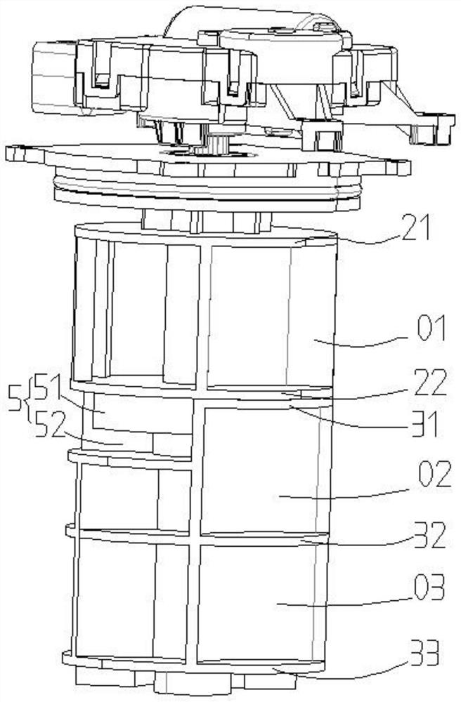
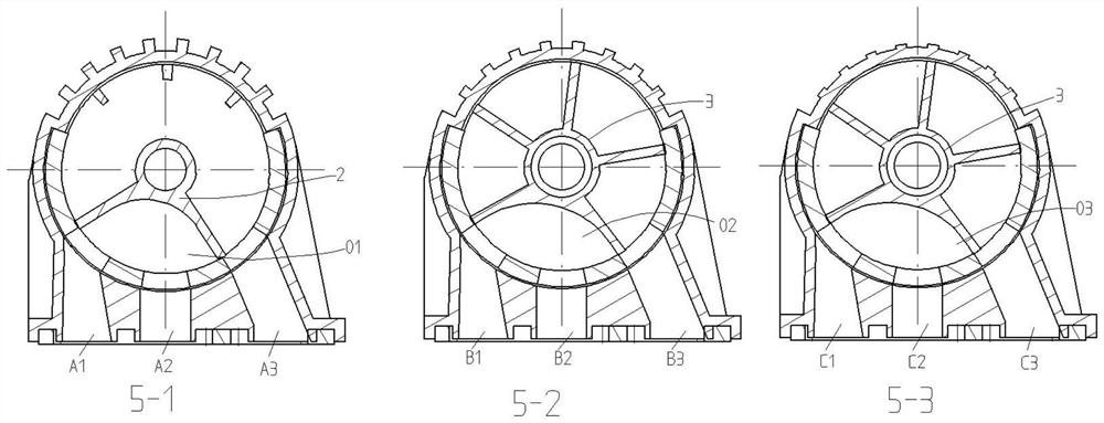
The proportional-adjustable pile-up valve comprises a driven driving valve element and a driven valve element arranged below the driving valve element, and the driving valve element and the driven valve element are rotationally arranged in a valve body; the driving valve element comprises a first top plate and a first bottom plate, and at least one set of first fluid channels which are communicated and can flow out of the valve body are formed between the first top plate and the first bottom plate. The driven valve element comprises a first plate body and a second plate body, and a plurality of second fluid channels capable of enabling fluid to flow outwards in the radial direction to the valve body are formed between the first plate body and the second plate body. A limiting structure capable of enabling the driving valve element to drive the driven valve element to rotate is arranged between the driving valve element and the driven valve element. The valve body is provided with a plurality of flow channel openings which can be communicated with the first fluid channel and the second fluid channel. The technical purpose of the invention is to provide the proportional-adjustable pile-up valve which is high in integration level and capable of reducing the cost, saving the space and reducing the weight.

Description

technical field [0001] The invention belongs to the technical field of fluid equipment, and particularly relates to a proportionally adjustable integrated valve. Background technique [0002] With the advancement of technology and the improvement of the control system, the control requirements for the fluid circuit are getting higher and higher, and the functions of the equipment with the fluid circuit are becoming more and more complete, involving vehicles, new energy vehicles and other equipment and devices, especially those involving To the energy exchange control of new energy vehicles, such as the temperature control of the passenger compartment, air conditioning system, power battery, electronic control system, etc. [0003] At present, the thermal management control system of new energy vehicles is becoming more and more complex. In order to realize various control and operation modes of the whole vehicle, the fluid circuit will involve multiple reversing valves and m...

Claims


Application Information

Patent Timeline
Patent Type & Authority Applications(China)
IPC IPC(8): F16K11/085F16K5/08F16K27/06
CPCF16K11/085F16K5/0407F16K5/08F16K27/065Y02T10/70
Inventor 曹威江坤唐俊屈怀里孙力飞杨曦
Owner CHENGDU WANYOU FILTER
Learn More