Working cylinder

A technology of working cylinder and working cavity, applied in manufacturing tools, workpiece edge parts, metal processing equipment, etc., can solve problems such as limiting the service life of threads, loosening screw connections, and high time investment.

Pending Publication Date: 2022-07-12
BUMACH ENG INT BV
View PDF0 Cites 0 Cited by
  • Summary
  • Abstract
  • Description
  • Claims
  • Application Information

AI Technical Summary

Problems solved by technology

[0010] In addition, final assembly requires a high investment of time and qualified labor
[0011] A further disadvantage is that additional means must be provided to prevent the screw connection from loosening
A final disadvantage is that there are dynamic loads on the thread due to the changing operating pressure, which limits the service life of the thread

Method used


Image

  • Working cylinder
  • Working cylinder
  • Working cylinder

Examples


Embodiment Construction

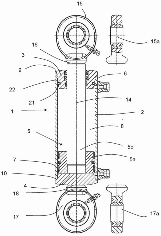
[0091] figure 1 An overview illustration of an embodiment of a working cylinder 1 as a differential working cylinder is shown. The working cylinder 1 has the cylinder liner 2 , the first closing part 3 , here designed as a guide closing part, the second closing part 4 , here designed as a bottom closing part, and the piston unit 5 . The piston unit 5 is constituted by the piston 5a and the piston rod 5b.

[0092] In this embodiment, the fixing module 15 on the piston rod side is arranged on the piston rod 5b and the fixing module 17 on the bottom side is arranged on the second closing part 4 which is designed as a bottom closing part. The two fixing modules 15 , 17 are respectively assigned fixing pins 15 a, 17 a. Said fixing modules 15, 17 and fixing pins 15a, 17a are not part of the present invention and are only shown for a better overview.

[0093] The piston unit 5 is arranged in the cylinder interior 8 in relation to the piston 5a and by means of the piston rod 5b, w...


PUM


Abstract

The invention relates to a working cylinder having a cylinder liner, a first closing part, a second closing part and a piston unit, the cylinder liner having a cylinder liner first end and a cylinder liner second end, the first closing part being arranged on the cylinder liner first end, the second closing part being arranged on the cylinder liner second end, and the piston unit being arranged on the cylinder liner first end. The first closing part is arranged at the first end of the cylinder liner, the second closing part is arranged at the second end of the cylinder liner, the cylinder liner and the closing parts form a cylinder inner cavity, the piston unit forms at least one working cavity in the cylinder inner cavity, and the piston unit penetrates through the first closing part in a sliding mode. The first closing part is integrally bonded to the cylinder liner by means of an annular first laser circumferential weld, and the second closing part is integrally bonded to the cylinder liner by means of an annular second laser circumferential weld, and the laser circumferential welds each form a fluid-tight sealing plane. An annular sealing ring is arranged axially spaced apart from the respective laser circumferential weld between each closing part and the inner wall of the cylinder liner, the sealing ring forming a pressure-separated ring section between each annular sealing ring and each laser circumferential weld.

Description

technical field [0001] The present invention relates to a welded working cylinder. Background technique [0002] Such working cylinders in various configurations are known from the prior art. [0003] All working cylinders of this type have cylinder liners as well as closing parts. According to the state of the art, the production of these working cylinders is usually carried out by screwing together the closing parts with the cylinder liners. Therefore, such working cylinders are also referred to in the prior art as screwing cylinders. [0004] Furthermore, it is known from the prior art to connect the bottom closing part to the cylinder liner by means of MAG welding (activated gas welding) and then only screw on the guide closing part. [0005] The threads of the cylinder liner and the closure member are usually formed by machining methods. [0006] According to the state of the art, both screwing cylinders and cylinders in which only one closing part is screwed and th...

Claims


Application Information

Patent Timeline
Patent Type & Authority Applications(China)
IPC IPC(8): F15B15/14B23K26/282B23K33/00
CPCF15B2215/30F15B15/1442B23K26/28F15B15/1438F15B15/17
Inventor 约瑟夫·布特
Owner BUMACH ENG INT BV
Why Eureka
Try Eureka