Ball part cleaning device and method for mechanical manufacturing
What is Al technical title?
Al technical title is built by PatSnap Al team. It summarizes the technical point description of the patent document.
A technology of machinery manufacturing and cleaning device, applied in the field of machinery, can solve the problems of insufficient cleaning of parts, low cleaning efficiency, difficult classification, etc., to meet the needs of use, reduce labor intensity, and facilitate classification.
Active Publication Date: 2022-07-15
NANJING UNIV OF INFORMATION SCI & TECH
View PDF9 Cites 0 Cited by
Summary
Abstract
Description
Claims
Application Information
AI Technical Summary
This helps you quickly interpret patents by identifying the three key elements:
Problems solved by technology
Method used
Benefits of technology
Problems solved by technology
[0002]Mechanical manufacturing During the manufacturing process of ball parts, oil stains, iron filings and other sundries will inevitably be attached, so it is necessary to clean the surface of ball parts Indispensable, the existing cleaning method is to manually place several parts on the rack for washing, which not only reduces the cleaning efficiency, but also increases the labor intensity of the workers. At the same time, many parts are stacked together for washing. Post-sorting is also a big problem. The increased labor intensity of workers will also lead to insufficient cleaning of some parts, and the cleaning effect is not ideal, making it difficult for shaft parts to meet the requirements of actual use.
Method used
Image
Click on the blue label to locate the original text in one second.
Reading with bidirectional positioning of images and text.
Examples
Embodiment Construction
[0035] The present invention will be described in further detail below in conjunction with the accompanying drawings and specific embodiments:
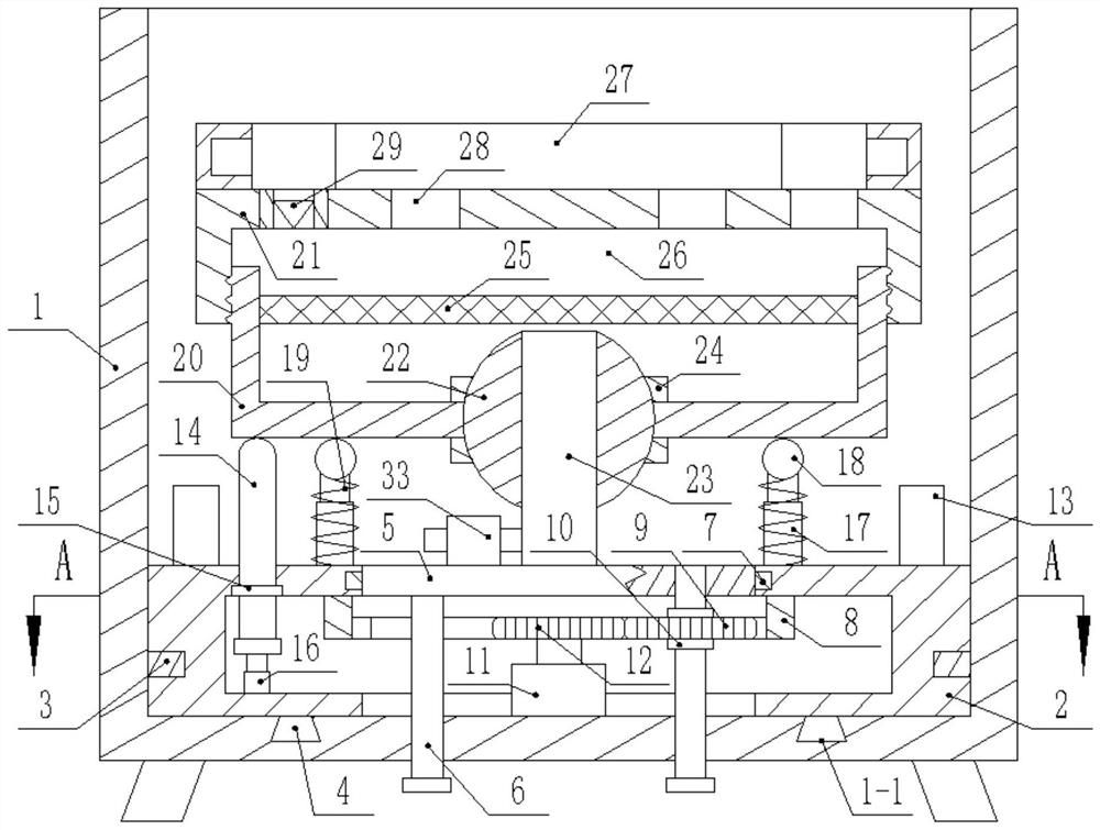
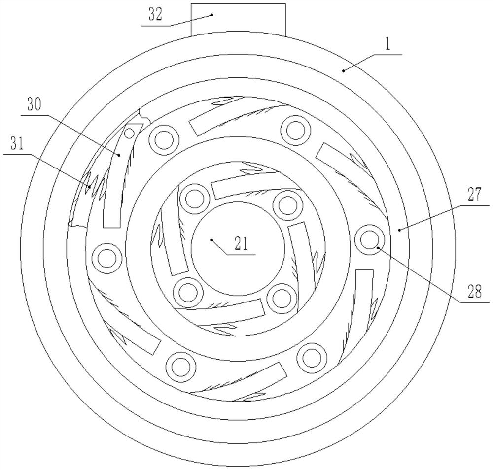
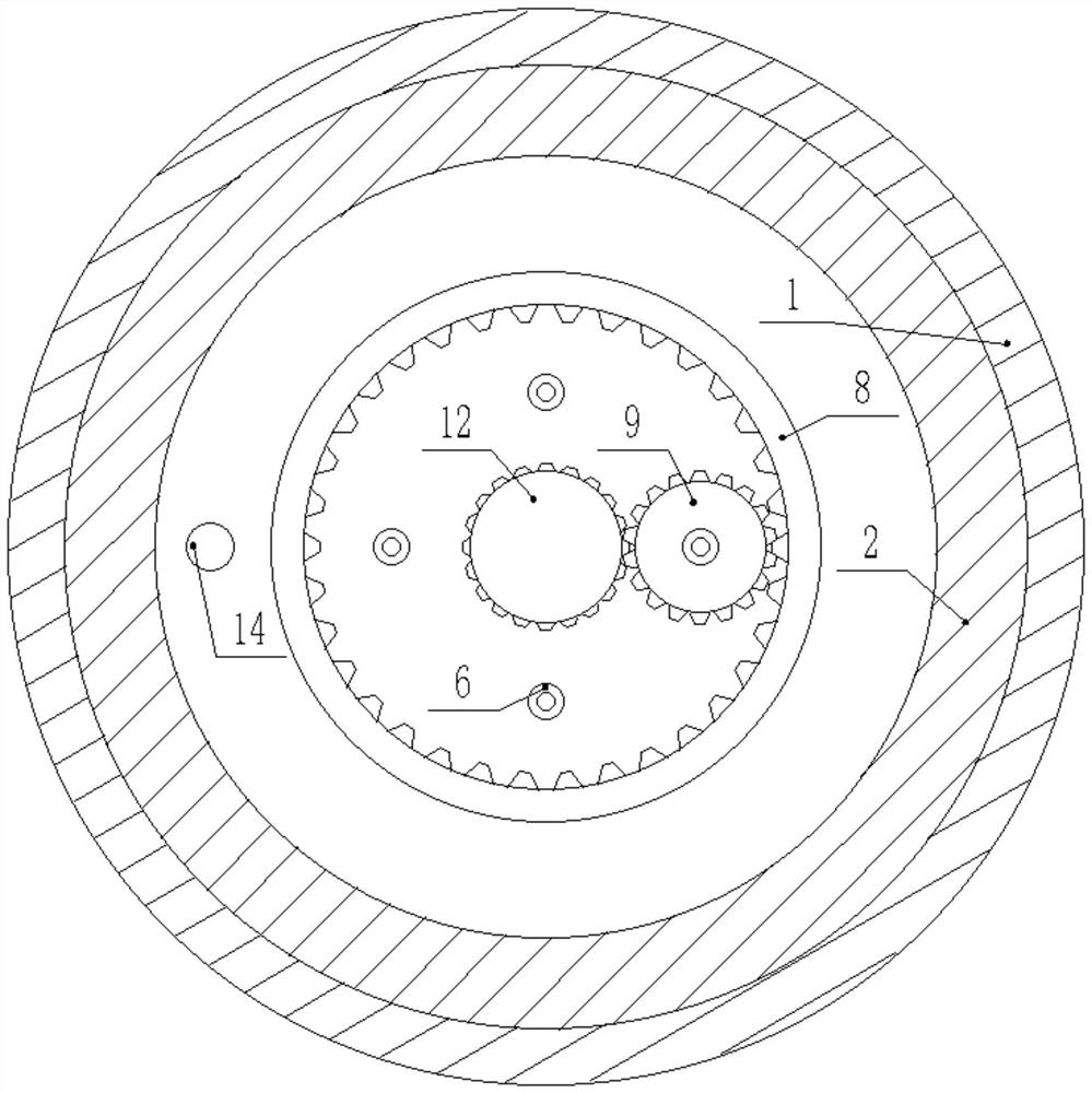
[0036] like figure 1 , figure 2 , image 3 , Figure 4 As shown, a device for cleaning ball parts for machinery manufacturing includes a mixing barrel 1, and a plurality of legs are fixedly and symmetrically connected to the bottom surface of the mixing barrel 1.
[0037] The inner bottom surface of the mixing barrel 1 is fitted and rotated with a first annular cylinder 2 , and the outer wall of the first annular cylinder 2 is fixed and embedded with a first sealing ring 3 through glue.
[0038] A dovetail groove 1-1 is annularly formed on the inner bottom surface of the mixing barrel 1, and a dovetail block 4 is fitted and slid in the dovetail groove 1-1.
[0039] A disc 5 is fitted and rotated in the first annular cylinder body 2, the top surface of the disc 5 is fixedly connected with a plurality of sewage pipes 6, and the bot...
PUM
Abstract
The invention discloses a ball part cleaning device and method for mechanical manufacturing. The device comprises an inner gear ring, a gear ring, a first limiting ring, a motor, a gear, a blade, a T-shaped sliding rod, a third sealing ring, an electric telescopic rod, a multi-section telescopic rod, a ball, a compression spring, an external thread barrel, an internal thread barrel, a steel ball, a first vertical pipe, a second limiting ring, a filter screen, an oil absorption felt, a second annular barrel, a second vertical pipe, a one-way valve, an arc-shaped brush, a spring and a material conveying pump. According to the device, ball parts of different models can be swung and fully cleaned at the same time.
Description
technical field [0001] The invention relates to the technical field of machinery, in particular to a device and method for cleaning ball parts for machinery manufacturing. Background technique [0002] In the process of machining and manufacturing ball parts, there will inevitably be sundries such as oil stains and iron filings attached to it. Therefore, it is essential to clean the surface of the ball parts. The existing cleaning method is to manually clean several parts. It is placed on the shelf for washing, which not only has low cleaning efficiency, but also increases the labor intensity of workers. At the same time, many parts are stacked together for washing. After cleaning, sorting is also a big problem, and the labor intensity of workers increases. It will lead to insufficient cleaning of some parts, and the cleaning effect is not ideal, making it difficult for shaft parts to meet the requirements of actual use. SUMMARY OF THE INVENTION [0003] In order to solve...
Claims
Application Information
Patent Timeline
Application Date:The date an application was filed.
Publication Date:The date a patent or application was officially published.
First Publication Date:The earliest publication date of a patent with the same application number.
Issue Date:Publication date of the patent grant document.
PCT Entry Date:The Entry date of PCT National Phase.
Estimated Expiry Date:The statutory expiry date of a patent right according to the Patent Law, and it is the longest term of protection that the patent right can achieve without the termination of the patent right due to other reasons(Term extension factor has been taken into account ).
Invalid Date:Actual expiry date is based on effective date or publication date of legal transaction data of invalid patent.