
Water hand long room and ship

A bosun's room and bosun's technology, which is applied to ship accessories, ships, crew equipment, etc., can solve the problems of unsatisfactory placement and installation of outfitting equipment, insufficient storage space, and low safety, so as to improve the utilization of internal space efficiency, increasing storage capabilities, and improving utilization

Pending Publication Date: 2022-07-15
GUANGZHOU SHIPYARD INTERNATIONAL LTD
View PDF6 Cites 0 Cited by
  • Summary
  • Abstract
  • Description
  • Claims
  • Application Information

AI Technical Summary

Problems solved by technology

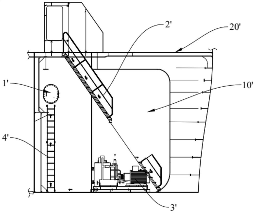
[0003] With the continuous optimization of the ship shape, the area of ​​the bosun's cabin 10' is continuously squeezed, and the height gradually increases from about three meters to six meters. The manhole 1' is located near the top of the boatswain's cabin 10'. The bottom deck of the bosun's cabin 10' can climb to the position of the manhole 1' with the help of the straight ladder 4', and then enter the chain locker through the manhole 1', resulting in a long journey from the boatswain's cabin 10' into the chain locker and less secure
At the same time, due to the increase in the height of the boatswain's cabin 10', it is difficult for the inclined ladder passage 2' to extend from the main deck 20' into the bilge deck of the boatswain's cabin 10', and it is easy to interfere with the hydraulic pump station 3'
In addition, the bottom deck of the boatswain's cabin 10' is severely insufficient in storage space due to the linear shrinkage of the outer panels, which cannot meet the placement and installation of outfitting equipment (shelving racks, etc.)

Method used


Image

  • Water hand long room and ship
  • Water hand long room and ship
  • Water hand long room and ship

Examples


Embodiment Construction

[0033] In order to make the technical problems solved by the present invention, the technical solutions adopted and the technical effects achieved more clearly, the technical solutions of the present invention are further described below with reference to the accompanying drawings and through specific embodiments. It should be understood that the specific embodiments described herein are only used to explain the present invention, but not to limit the present invention. In addition, it should be noted that, for the convenience of description, the accompanying drawings only show some but not all of the parts related to the present invention.

[0034] In the description of the present invention, unless otherwise expressly specified and limited, the terms "connected", "connected" and "fixed" should be understood in a broad sense, for example, it may be a fixed connection, a detachable connection, or an integrated ; It can be a mechanical connection or an electrical connection; it...


PUM


Abstract

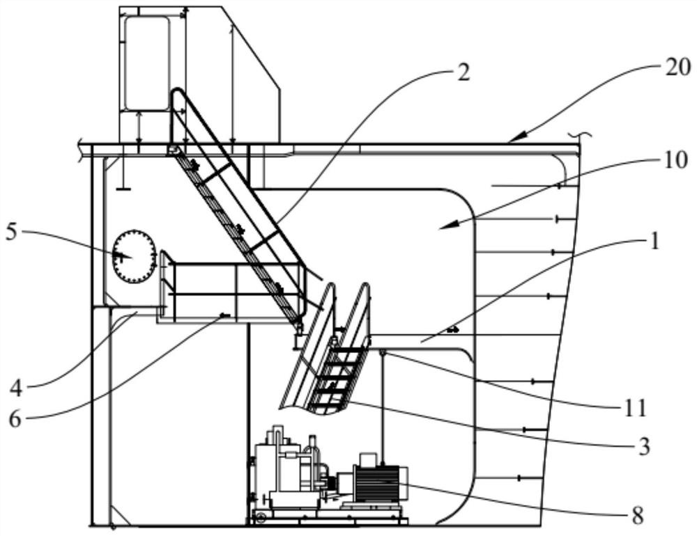
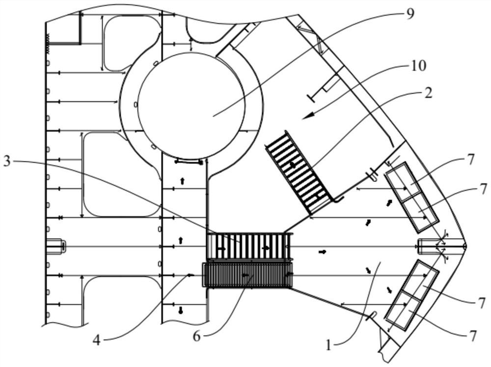
The invention relates to the technical field of ship construction, in particular to a water hand long room and a ship. An inlet communicated with the main deck is formed in the top of the water hand long chamber, and a manhole communicated with the chain locker is formed in the inner wall of the water hand long chamber. The water hand long chamber comprises a first bay platform, a first inclined ladder, a second inclined ladder and a second bay platform, and the first bay platform is arranged on the front wall of the water hand long chamber and divides the water hand long chamber into compound cabins. One end of the first inclined ladder is lapped on the inlet of the water hand long chamber, and the other end is lapped on the first floating platform. One end of the second inclined ladder is lapped on the bottom deck of the water hand long room, and the other end is lapped on the first floating platform. The second bay platform is arranged on the rear wall of the water hand long chamber and located below the manhole so as to enter the manhole through the second bay platform, and the first bay platform is connected with the second bay platform. The ship comprises the watercraft room, so that personnel can safely and conveniently reach the bottom deck and the manhole of the watercraft room, the internal layout of the watercraft room is optimized, and the internal space utilization rate of the watercraft room is improved.

Description

technical field [0001] The invention relates to the technical field of ship construction, in particular to a bosun's room and a ship. Background technique [0002] like figure 1 As shown, in the outfitting arrangement of the existing bosun's room 10', the inclined ladder passage 2' is used to lead to the area of ​​the main deck 20'. For the comfort and safety of passage, the angle of the inclined ladder passage 2' generally does not exceed 55°. In addition, the bottom deck of the bosun's room 10' is arranged with shelves, a cable storage area, a hanging port, a hydraulic pump station 3', a manhole 1' leading to the chain locker, etc., so the bosun's room 10' is required to have sufficient big space. [0003] With the continuous optimization of the ship shape, the area of ​​the captain's room 10' is continuously squeezed, and the height gradually increases from about three meters to six meters. The manhole 1' is located near the top of the captain's room 10'. The bottom d...

Claims


Application Information

Patent Timeline
Patent Type & Authority Applications(China)
IPC IPC(8): B63B29/00B63B29/20
CPCB63B29/00B63B29/20
Inventor 马丹任平首志平何建晖张丹丹
Owner GUANGZHOU SHIPYARD INTERNATIONAL LTD
Learn More