
Pulse width modulation two-output circuit

A technology of output circuit and pulse width, which is applied in the field of pulse width modulation two-way output circuit, and can solve problems such as complex layout of pulse width modulation circuit

Inactive Publication Date: 2019-02-15
青岛艾普欧盛电子科技有限公司
View PDF5 Cites 0 Cited by
  • Summary
  • Abstract
  • Description
  • Claims
  • Application Information

AI Technical Summary

Problems solved by technology

[0002] Most of the pulse width modulation circuits in the prior art are driven by transistors and then output two pulse width modulation output circuit waveforms. The waveforms are filtered and output by the inductor and capacitor oscillator circuits. There are many transistor clinkers in the application, so the layout of this form of pulse width modulation circuit is mostly very complicated

Method used


Image

  • Pulse width modulation two-output circuit
  • Pulse width modulation two-output circuit
  • Pulse width modulation two-output circuit

Examples


Embodiment Construction

[0044] In order to solve the problems in the prior art, the present invention provides a pulse width modulation two-way output circuit, which not only reduces the number of applied circuit components, but also is more suitable for practical use.

[0045] In order to further explain the technical means and effects adopted by the present invention to achieve the intended purpose of the invention, the specific implementation, structure, Features and their functions are described in detail below. In the following description, different "one embodiment" or "embodiment" do not necessarily refer to the same embodiment. Furthermore, the features, structures, or characteristics of one or more embodiments may be combined in any suitable manner.

[0046] The term "and / or" in this article is just an association relationship describing associated objects, which means that there can be three relationships, for example, A and / or B. The specific understanding is: A and B can be included at t...


PUM


Abstract

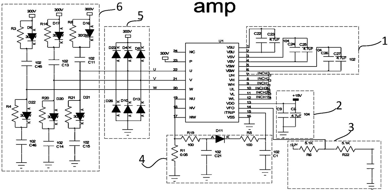
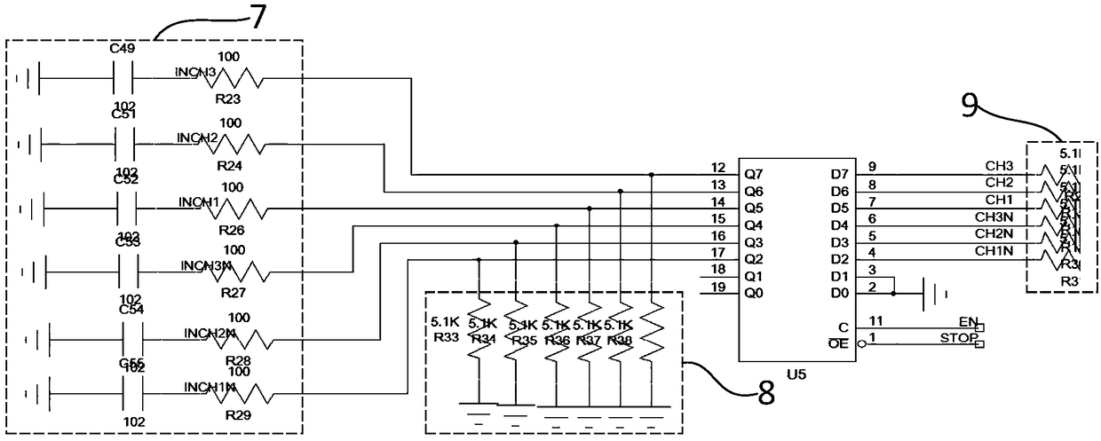
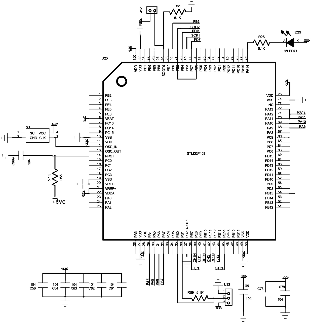
The invention discloses a pulse width modulation two-output circuit and belongs to the field of circuit technology. The pulse width modulation two-output circuit comprises an insulated gate bipolar transistor U1, a UVW three-side power end filtering capacitor circuit (1), a power end filtering circuit (2), a fault signal output circuit (3), a UVW three-phase output current detection circuit (4), aUVW output terminal power supply clamping protection circuit (5), a UVW terminal output protection absorption circuit (6), a singlechip U5 and a peripheral circuit thereof, wherein the UVW three-sidepower end filtering capacitor circuit (1), the power end filtering circuit (2), the fault signal output circuit (3), the UVW three-phase output current detection circuit (4), the UVW output terminalpower supply clamping protection circuit (5), the UVW terminal output protection absorption circuit (6), the singlechip U5 and the peripheral circuit thereof are respectively connected with the insulated gate bipolar transistor U1 by virtue of a corresponding pin. The circuit disclosed by the invention has the advantage that number of applied circuit elements is greatly reduced.

Description

technical field [0001] The invention relates to the field of circuit technology, in particular to a pulse width modulation two-way output circuit. Background technique [0002] Most of the pulse width modulation circuits in the prior art are driven by transistors and then output two pulse width modulation output circuit waveforms. The waveforms are filtered and output by the inductor and capacitor oscillator circuits. There are many transistor clinkers used, so the layout of this form of pulse width modulation circuit is mostly very complicated. Contents of the invention [0003] In view of this, the present invention provides a pulse width modulation two-way output circuit, which not only reduces the number of applied circuit components, but also is more suitable for practical use. [0004] In order to achieve the above object, the technical scheme of the pulse width modulation two-way output circuit provided by the present invention is as follows: [0005] The pulse wi...

Claims


Application Information

Patent Timeline
IPC IPC(8): H03K7/08
CPCH03K7/08
Inventor 于钦先韩庆江
Owner 青岛艾普欧盛电子科技有限公司
Learn More