U-shaped glass wall surface structure

A glass and U-shaped technology, applied in the direction of walls, building components, building structures, etc., can solve the problems of affecting the gas environment, fracture, and air circulation, etc., and achieve the effect of improving the gas environment

Pending Publication Date: 2022-07-15
深圳市晶宫建筑装饰集团有限公司
View PDF0 Cites 0 Cited by
  • Summary
  • Abstract
  • Description
  • Claims
  • Application Information

AI Technical Summary

Problems solved by technology

[0004] However, in the traditional glass curtain wall structure composed of double-layer U-shaped glass, the glass installation method is fixed, so when the glass wall is hit or squeezed, the joint between the glass wall and the concrete building will be under compressive stress. In addition, the space formed by the double-layer U-shaped glass has no internal air circulation, and water vapor and biological colonies cannot be discharged, which seriously affects the gas environment in the space. , and will cause corrosion or yellowing of the glass, etc.

Method used


Image

  • U-shaped glass wall surface structure
  • U-shaped glass wall surface structure
  • U-shaped glass wall surface structure

Examples


Embodiment 1

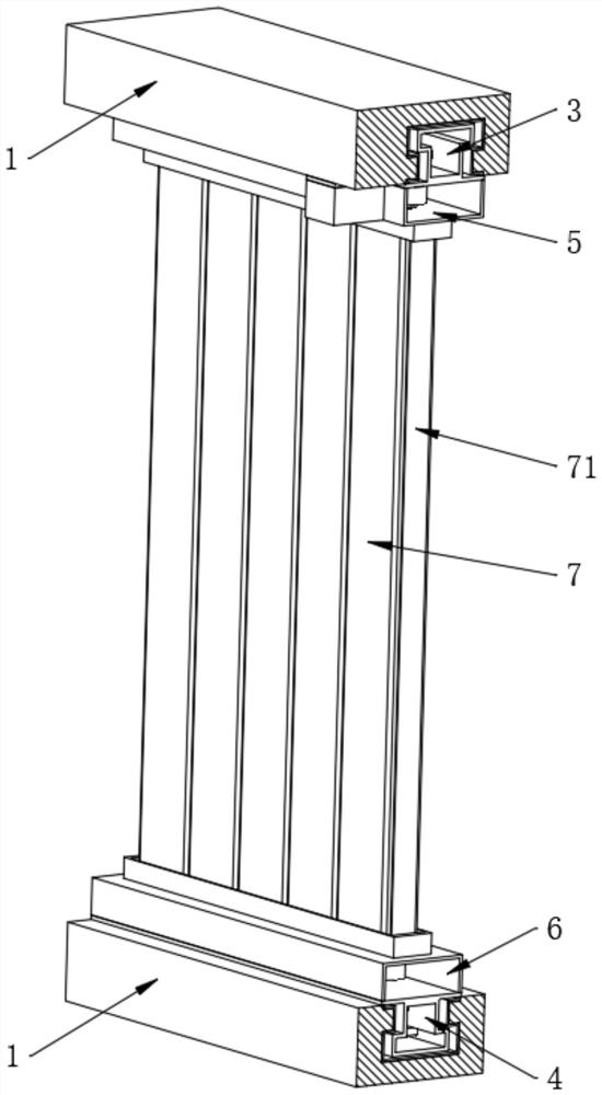
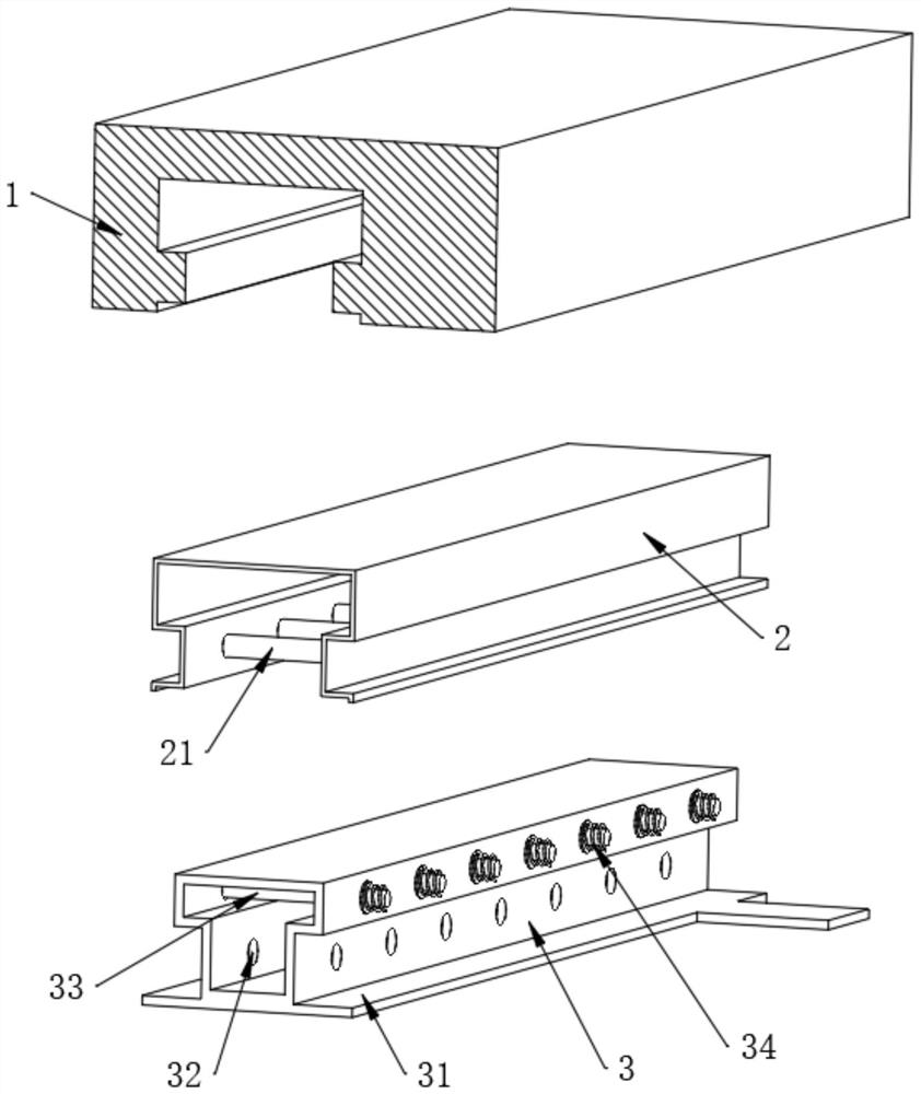
[0036] Refer to the attached figure 2 , the inner wall of the embedded steel frame 2 is equidistantly provided with guide rods 21, the inner wall of the top composite steel frame 3 is provided with guide holes 32 corresponding to the positions of the guide rods 21, and the guide rods 21 move through the guide holes 32, and the guide rods 21 It plays the role of guiding the movement of the top combined steel frame 3 .

[0037] Refer to the attached figure 2 , the bottom of the top combined steel frame 3 is fixedly provided with a connecting plate 31, the top of the top combined steel frame 3 is equidistantly inserted with an inner strut 33, and the outer walls of both sides of the top combined steel frame 3 are equally spaced with springs 34, and The spring 34 is sleeved on the outer surface of the inner strut 33. The top composite steel frame 3 and the bottom composite steel frame 4 have the same structure and are arranged in a mirror image. When the glass wall is impacted, t...

Embodiment 2

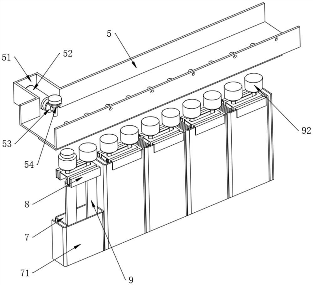
[0040] Refer to the attached image 3 , the top glass frame 5 is fixedly connected with the connecting plate 31, one side outer wall of the top glass frame 5 is fixedly provided with a side opening shell 51, the inside of the side opening shell 51 is fixedly installed with a working motor 52, and the output end of the working motor 52 is fixedly installed with a The first helical gear 53, the inner end of the top glass frame 5 is rotatably installed with the second helical gear 54, and the first helical gear 53 meshes with the second helical gear 54.

[0041] Refer to the attached Figure 4 , both ends of the triangular transparent frame 9 are fixedly provided with end rods 91, and the end rods 91 respectively extend to the interior of the top glass frame 5 and the bottom glass frame 6, and the ends of the end rods 91 are fixedly connected with end sprockets 92, And the end sprockets 92 are connected by a set chain 93, and the end sprocket 92 located at one end of the top gla...

Embodiment 3

[0046] Refer to the attached Figure 5 , the half-end sprocket 92 located inside the bottom glass frame 6 has bottom gears 94 fixedly installed on its lower surface, and all bottom gears 94 have the same spacing. During the regular rotation of the three-edged transparent frame 9, part of the three-edged transparent The bottom end of the frame 9 will drive the bottom gear 94 to rotate together.

[0047] Refer to the attached Figure 5 and Image 6 , the linkage pneumatic device 11 also includes a pneumatic casing 1101, the number of the pneumatic casing 1101 is the same as the number of the bottom gear 94, the lower surface of one end of the pneumatic casing 1101 is rotatably installed with a power gear 1102, and the power gear 1102 and the bottom gear 94 The crankshaft 1105 is fixedly connected with the power gear 1102, the end of the crankshaft 1105 is connected with the connecting rod 1106 in rotation, and the end of the connecting rod 1106 is connected with the piston 110...


PUM


Abstract

The invention belongs to the technical field of glass curtain walls, and particularly relates to a U-shaped glass wall structure which comprises a building wall, a top glass frame and a bottom glass frame are assembled at the upper end and the lower end of inner U-shaped light-transmitting glass and the upper end and the lower end of outer U-shaped color-transmitting glass correspondingly, and a top combined steel frame is fixedly assembled on the upper surface of the top glass frame; a bottom combined steel frame is fixedly assembled on the lower surface of the bottom glass frame, triangular transparent frames are rotationally installed in the assembling space of the inner U-shaped light-transmitting glass and the assembling space of the outer U-shaped color-transmitting glass, air purifiers are fixedly arranged in the top glass frame at equal intervals, and linkage pneumatic devices are fixedly arranged in the bottom glass frame at equal intervals. Impact force borne by the glass wall can be absorbed, then the possibility that the ends of the glass wall are broken is avoided, meanwhile, the display, decoration and propaganda functions of the glass wall are added, the monotonous use mode of traditional monotonous U-shaped glass is changed, and finally the air environment in the glass wall can be automatically purified.

Description

technical field [0001] The invention belongs to the technical field of glass curtain walls, and in particular relates to a U-shaped glass wall structure. Background technique [0002] U-shaped glass (also known as channel glass) is continuously produced by the method of rolling first and then forming. It is named because of its "U"-shaped cross-section; there are many varieties of U-shaped glass, which have ideal light transmittance, Thermal insulation, thermal insulation and high mechanical strength, not only widely used, easy construction, but also has a unique architectural and decorative effect, and can save a lot of light metal profiles, so it is used by urban and rural buildings in many countries in the world. [0003] Problems existing in the prior art: [0004] However, in the traditional glass curtain wall structure composed of double-layer U-shaped glass, the installation method of the glass is fixed, so when the glass wall is hit or squeezed, the splicing point b...

Claims


Application Information

Patent Timeline
Patent Type & Authority Applications(China)
IPC IPC(8): E04B2/88B01D46/62B01D53/26F21V33/00
CPCE04B2/88E04B2/885B01D53/26F21V33/00
Inventor 丘远存周俊彭永雄刘德志柯学
Owner 深圳市晶宫建筑装饰集团有限公司
Why Eureka
Try Eureka