Drill bit based on central multi-edge tooth modulation pulse jet flow and drilling method thereof

A technology for modulating pulses and drill bits, which is applied in drill bits, drilling with liquid/gas jets, and earth-moving drilling, etc. It can solve the problems of increasing hydraulic energy loss, difficult to apply in a large range, changing the structure of drilling tools, etc., and reduce the surrounding rock pressure. , Wide range of application, the effect of improving drilling speed

Pending Publication Date: 2022-07-15
CHINA PETROLEUM & CHEM CORP +1
View PDF0 Cites 0 Cited by
  • Summary
  • Abstract
  • Description
  • Claims
  • Application Information

AI Technical Summary

Problems solved by technology

[0003] Field practice has shown that modulating the pulse jet for the drill bit can improve the effect of rock cleaning at the bottom of the well and thus increase the drilling speed. A series of pulse jet tools have been developed for this purpose. Although they have the effect of increasing the speed, they have changed the structure of the drilling tool and increased hydraulic energy consumption. , difficult to be widely used in directional wells and horizontal wells

Method used


Image

  • Drill bit based on central multi-edge tooth modulation pulse jet flow and drilling method thereof
  • Drill bit based on central multi-edge tooth modulation pulse jet flow and drilling method thereof
  • Drill bit based on central multi-edge tooth modulation pulse jet flow and drilling method thereof

Examples


Embodiment Construction

[0030] It should be understood that the specific embodiments described herein are only used to explain the present invention, but not to limit the present invention.

[0031] It should be noted that in the description of the present invention, the terms "horizontal", "longitudinal", "upper", "lower", "front", "rear", "left", "right", "vertical", The orientation or positional relationship indicated by "horizontal", "top", "bottom", "inside", "outside", etc. is based on the orientation or positional relationship shown in the accompanying drawings, and is only for the convenience of describing the present invention and simplifying the description, and It is not indicated or implied that the indicated device or element must have a particular orientation, be constructed and operate in a particular orientation, and therefore should not be construed as limiting the invention. Furthermore, the terms "first," "second," etc. are used for descriptive purposes only and should not be const...


PUM


Abstract

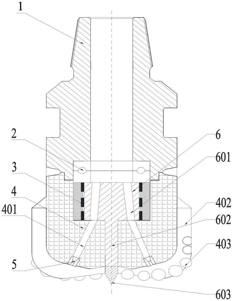
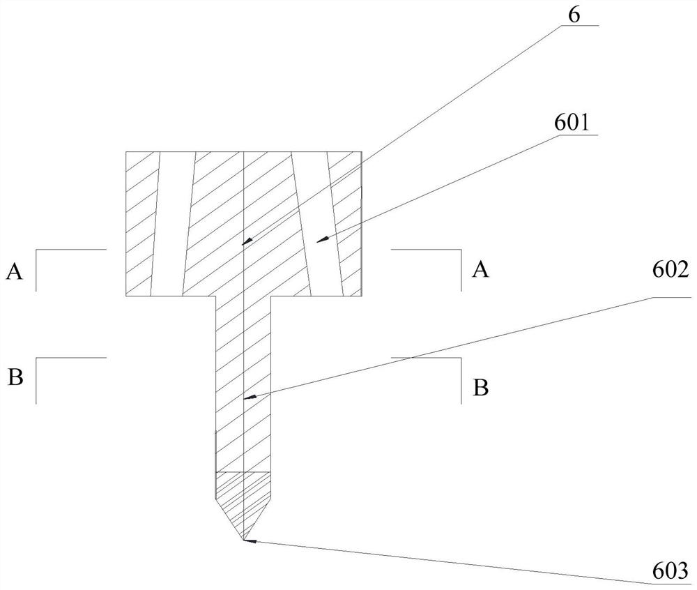
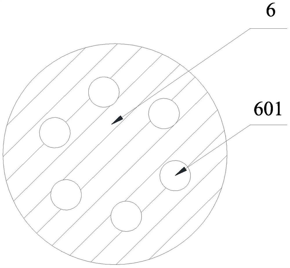
The drill bit comprises a drill bit connector, a drill bit crown part, a nozzle and a flow adjusting body, a blade is arranged on the outer side of the drill bit crown part, a plurality of cutting teeth are arranged on the blade, and the drill bit connector and the drill bit crown part jointly form a hollow channel. The flow adjusting body is supported in the hollow channel, the end of the flow adjusting body protrudes out of the drill bit crown, the part, protruding out of the drill bit crown, of the flow adjusting body is a center press-in rock crushing tooth, a drill bit flow channel communicated with the hollow channel is formed in the drill bit crown, and a flow adjusting body overflowing hole is formed in the flow adjusting body. The top end of the flow adjusting body overflowing hole is communicated with the hollow channel in the drill bit connector, the bottom end of the flow adjusting body overflowing hole can be communicated with the drill bit flow channel when the flow adjusting body rotates, and a nozzle is installed at the bottom end of the drill bit flow channel. According to the drill bit for modulating the pulse jet flow based on the center multi-edge tooth, the pulse jet flow is generated on the premise that no other tools are connected, the aim of improving the well bottom rock cleaning effect is achieved, and the drilling speed is increased.

Description

technical field [0001] The invention relates to the technical field of drill bit structures, in particular to a drill bit and a drilling method based on a central polygonal tooth modulated pulse jet. Background technique [0002] Various types of drill bits, such as 3D tooth drill bits, high-performance tooth drill bits, dual-stage drill bits and self-adaptive drill bits, have been developed at home and abroad, and have achieved a certain speed-up effect, but they still do not meet the expectations of the drilling site. the problem. [0003] Field practice shows that modulating a pulse jet for the drill bit can improve the bottom hole cleaning effect and thus increase the drilling speed. For this purpose, a series of pulse jet tools have been developed. Although the speed increase effect is achieved, it changes the structure of the drilling tool and increases the hydraulic energy loss. , it is difficult to be widely used in directional wells and horizontal wells. If a dril...

Claims


Application Information

Patent Timeline
Patent Type & Authority Applications(China)
IPC IPC(8): E21B10/42E21B10/60E21B7/18
CPCE21B10/42E21B10/602E21B7/18
Inventor 周忠亚秦文斌黄权刘永旺卢和平李俊
Owner CHINA PETROLEUM & CHEM CORP
Why Eureka
Try Eureka