
Method and device for testing arcing voltage parameters of direct-current electric arc furnace

A DC electric arc furnace and arc starting voltage technology, applied in the field of industrial smelting, can solve problems such as the complexity of the DC electric arc furnace power supply equipment system, the difficulty of system control, and the impact on smelting stability, so as to optimize the arc starting process and improve industrial smelting. Efficiency and the effect of shortening the arc start time

Pending Publication Date: 2022-07-15
中冶赛迪电气技术有限公司
View PDF0 Cites 1 Cited by
  • Summary
  • Abstract
  • Description
  • Claims
  • Application Information

AI Technical Summary

Problems solved by technology

[0003] However, the DC electric arc furnace power supply equipment system is relatively complex. Compared with the AC electric arc furnace system, an AC-DC conversion module is added, and the output voltage and current of the power supply equipment need to be controlled in real time during the entire smelting process, making the system control difficult.
Among them, during the arcing process of smelting, due to the change of the contact area between the electrode and the charge material or the difference in the conductivity of the charge material, the same arc starting voltage is prone to current shock or frequent arc interruption, which affects the overall smelting stability and reduces smelting efficiency.

Method used


Image

  • Method and device for testing arcing voltage parameters of direct-current electric arc furnace
  • Method and device for testing arcing voltage parameters of direct-current electric arc furnace
  • Method and device for testing arcing voltage parameters of direct-current electric arc furnace

Examples


Embodiment Construction

[0037] The embodiments of the present invention are described below through specific specific examples, and those skilled in the art can easily understand other advantages and effects of the present invention from the contents disclosed in this specification. The present invention can also be implemented or applied through other different specific embodiments, and various details in this specification can also be modified or changed based on different viewpoints and applications without departing from the spirit of the present invention. It should be noted that the drawings provided in the following embodiments are only used to illustrate the basic idea of ​​the present invention in a schematic manner, and the following embodiments and features in the embodiments can be combined with each other without conflict.

[0038] Among them, the accompanying drawings are only for illustrative description, and represent only schematic diagrams, not physical drawings, and should not be co...


PUM

PropertyMeasurementUnit
compressive strengthaaaaaaaaaa

Abstract

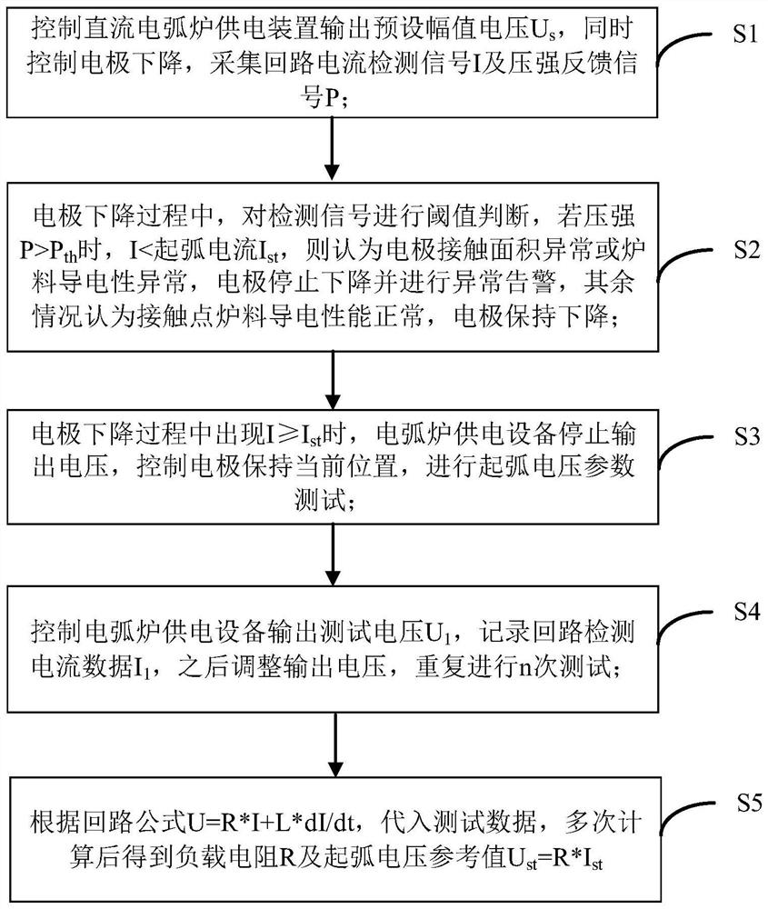
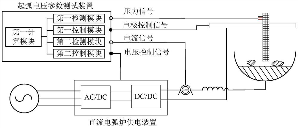
The invention relates to a method and a device for testing arcing voltage parameters of a direct-current electric arc furnace, and belongs to the technical field of industrial smelting. The method comprises the steps that S1, a direct-current electric arc furnace power supply device is controlled to output preset amplitude voltage Us, meanwhile, an electrode is controlled to descend, and a loop current signal I and a pressure intensity signal P are collected; s2, in the electrode descending process, threshold judgment is carried out on a detection signal; s3, when I is larger than or equal to Ist in the electrode descending process, the electric arc furnace power supply equipment stops outputting voltage, the electrode is controlled to be kept at the current position, and an arcing voltage parameter test is conducted; s4, repeating the test for n times; and S5, substituting test data, and calculating for multiple times to obtain a load resistance R and an arcing voltage reference value Ust = R * Ist. Reliable arcing voltage parameters can be provided for a power supply device of the direct-current electric arc furnace, the arcing process of the direct-current electric arc furnace is optimized, the arcing current impact is reduced, and the phenomenon of arcing failure caused by the difference of furnace charge conductivity is avoided.

Description

technical field [0001] The invention belongs to the technical field of industrial smelting, and relates to a method and a device for testing arc voltage parameters of a DC electric arc furnace. Background technique [0002] The DC electric arc furnace is developed on the basis of the ultra-high-power electric arc furnace. It is a combination of various related technologies of the ultra-high-power electric arc furnace and contemporary high-efficiency, high-power semiconductor converter technology. Compared with the traditional AC electric arc furnace, the DC electric arc furnace has obvious advantages in arc stability and heat transfer. At the same time, its smelting process has less interference and impact on the power grid, and has a high grid-side power factor. It is an important development in industrial smelting. trend. [0003] However, the DC electric arc furnace power supply equipment system is more complicated. Compared with the AC electric arc furnace system, an AC...

Claims


Application Information

Patent Timeline
Patent Type & Authority Applications(China)
IPC IPC(8): F27B3/28
CPCF27B3/28
Inventor 肖学文赵聪干永革郝亚川孙倩倩任亚葱王硕
Owner 中冶赛迪电气技术有限公司
Learn More