Supercharge Your Innovation With Domain-Expert AI Agents!

Cleaning head for vacuum cleaning appliance

A vacuum cleaning, cleaning head technology, applied in the field of cleaning head or floor tools, rotary driven agitator assembly, which can solve the problem of low flow rate

Pending Publication Date: 2022-07-15
DYSON TECH LTD
View PDF0 Cites 0 Cited by
  • Summary
  • Abstract
  • Description
  • Claims
  • Application Information

AI Technical Summary

Problems solved by technology

However, even at high flow rates, there may be areas within the cleaning head where the flow rate is relatively low, especially at the end of the cleaning head

Method used


Image

  • Cleaning head for vacuum cleaning appliance
  • Cleaning head for vacuum cleaning appliance
  • Cleaning head for vacuum cleaning appliance

Examples


Embodiment Construction

[0034] Specific embodiments of the present invention will now be described, in which numerous features will be discussed in detail in order to provide a thorough understanding of the inventive concepts defined in the appended claims. It will be apparent to the reader, however, that the present invention may be practiced without specific details and, in some instances, well-known methods, techniques and structures have not been described in detail in order to avoid unnecessarily obscuring the concepts of the present invention .

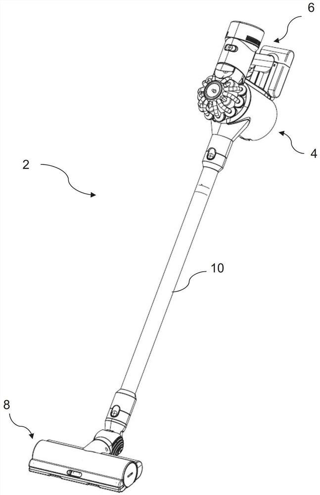
[0035] figure 1 A known vacuum cleaning appliance or vacuum cleaner 2 is shown comprising a dirt and dust separation unit 4 , a motor-driven fan unit 6 and a cleaning head 8 . The vacuum cleaner 2 also includes a wand 10 connecting the dirt and dust separating unit 4 and the cleaning head 8 . The motor-driven fan unit 6 draws the dirt-laden air from the surface to be cleaned (eg floor surface) via the cleaning head 8 to the dirt and dust separation u...


PUM


Abstract

The present invention relates to a cleaning head 10 for a vacuum cleaning appliance 2, the cleaning head 10 comprising a body 12 defining an agitator chamber 34 having an inner surface 50 and an agitator assembly 36 supported within the agitator chamber 34. The agitator assembly 36 includes an elongate body 42 configured to rotate about a longitudinal axis thereof, an agitator structure 44 including at least one agitator row 46 extending from an outer surface 48 of the elongate body 42 for engaging a surface to be cleaned during use, and a compressor structure 56. The compressor structure 56 includes at least one compressor element 58 extending from the outer surface 48 of the elongate body 42 such that a radial distance defined between the at least one compressor element 58 and the inner surface 50 of the agitator cavity 34 is less than a radial distance defined between the outer surface 48 of the elongate body 42 and the inner surface 50 of the agitator cavity 34.

Description

technical field [0001] The present invention relates generally to vacuum cleaner appliances, and more particularly to a cleaning head or floor implement forming part of the appliance. The invention particularly relates to rotationally driven agitator assemblies for use in such cleaning heads, whether the cleaning heads are permanently or removably affixed to their respective implements. The type of vacuum cleaner appliance is not critical to the present invention, so the present invention may relate to so-called bagged or bagless vacuum cleaner appliances. Background technique [0002] Vacuum cleaning appliances, or more simply "vacuum cleaners", generally include a body equipped with a suction source and a dust separator, and a cleaning head that is connected to the dust separator, usually by a detachable coupling. The cleaning head has a suction opening through which the cleaning head engages with the surface to be cleaned and through which dust laden air is drawn into th...

Claims


Application Information

Patent Timeline
IPC IPC(8): A47L5/30A47L9/04
CPCA47L9/0477A47L5/30
Inventor M.马瑟斯
Owner DYSON TECH LTD
Features
  • R&D
  • Intellectual Property
  • Life Sciences
  • Materials
  • Tech Scout
  • Unparalleled Data Quality
  • Higher Quality Content
  • 60% Fewer Hallucinations
Learn More