Fiber-reinforced composite material and sandwich structure

A fiber-reinforced, composite material technology, applied in the field of fiber-reinforced composite materials, can solve problems such as the decline of mechanical properties, and achieve the effect of light weight and mechanical properties

Pending Publication Date: 2022-07-15
TORAY IND INC
View PDF3 Cites 0 Cited by
  • Summary
  • Abstract
  • Description
  • Claims
  • Application Information

AI Technical Summary

Problems solved by technology

However, such a porous fiber-reinforced composite material has the following problem: the more the proportion of pores is increased for the purpose of weight reduction, the more rapidly the mechanical properties decrease.

Method used


Image

  • Fiber-reinforced composite material and sandwich structure
  • Fiber-reinforced composite material and sandwich structure
  • Fiber-reinforced composite material and sandwich structure

Examples


Embodiment 1

[0135] As the reinforcing fiber base material (B'), the carbon fiber nonwoven fabric produced in the above-mentioned manner is prepared to be folded into a Figure 10 The weight per unit area obtained from the cross-sectional structure shown is 100 g / cm 2folded substrate. At this time, when the prepreg is produced, in the pair of folds 8 adjacent to the reinforcing fiber base material (B'), the linear distance (Lr) between the pair of adjacent folds is 0 mm, that is, the contact is made Folding is carried out, and the distance (Lf) between the adjacent pair of folds along the carbon fiber nonwoven fabric is 10 mm, and one fold of the adjacent pair of folds is used as the starting point until it exists on the opposite side of the pair of folds. Fold it so that the straight-line distance (Ls) to the other crease in the direction becomes 5 mm. In addition, it folded so that the composition ratio 9 of a pair of folds that were close when the front and back surfaces of the folded...

Embodiment 2

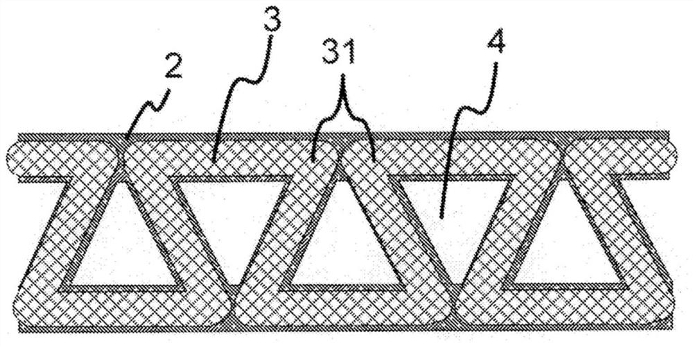
[0138] As the reinforcing fiber base material (B'), except that the configuration of the folded base material was changed so that Lr was 1 mm and Lf was 9 mm, processing was carried out in the same manner as in Example 1 to obtain a prepreg and a fiber-reinforced composite material. . The resulting fiber-reinforced composite material has figure 1 The illustrated cross-section surrounded by three sides of the fiber-reinforced structure is a substantially triangular opening. The openings of the cavity are aligned in the in-plane direction. The evaluation results are shown in Table 1.

Embodiment 3

[0140] As the reinforcing fiber base material (B'), except that the configuration of the folded base material was changed so that Lr was 2 mm and Lf was 8 mm, processing was carried out in the same manner as in Example 1 to obtain a prepreg and a fiber-reinforced composite material. . The resulting fiber-reinforced composite material has Figure 13 The cross-section of the three sides of the fiber-reinforced structural portion as shown is a substantially trapezoidal opening. The openings of the cavity are aligned in the in-plane direction. The evaluation results are shown in Table 1.


PUM

PropertyMeasurementUnit
Number average fiber lengthaaaaaaaaaa
Average pore diameteraaaaaaaaaa
Lengthaaaaaaaaaa

Abstract

The purpose of the present invention is to obtain a fiber-reinforced composite material that achieves both lightweight properties and mechanical properties at a high level. The present invention is a fiber-reinforced composite material having: a fiber-reinforced structure part that contains a resin (A) and reinforcing fibers (B), and that has an in-plane orientation part in which the average fiber orientation angle of the reinforcing fibers (B) is 0-45 DEG, and an out-plane orientation part in which the average fiber orientation angle of the reinforcing fibers (B) is greater than 45 DEG and 90 DEG; and a cavity section that is partitioned by the in-plane orientation section and the out-of-plane orientation section of the fiber-reinforced structure section.

Description

technical field [0001] The present invention relates to fiber-reinforced composite materials that achieve both lightweight and mechanical properties. Background technique [0002] Fiber-reinforced composite materials that use thermosetting resins and thermoplastic resins as a matrix and are combined with reinforcing fibers such as carbon fibers and glass fibers are used because of their light weight, excellent mechanical properties such as strength and rigidity, flame retardancy, and corrosion resistance. It is used in a large number of fields such as aviation and aerospace, automobiles, railway vehicles, ships, civil engineering, electronic equipment, industrial machinery, and sporting goods. On the other hand, from the viewpoints of improvement in fuel consumption and portability, further weight reduction is required as a member and a casing, and a porous fiber-reinforced composite material having pores formed therein has also been developed. However, such a porous fiber-...

Claims


Application Information

Patent Timeline
IPC IPC(8): B29C70/10B29B11/16B29K105/08B29K105/12B29C70/40
CPCB29C70/003B29C70/0035B29C70/081B29C70/12B29C53/24B29C70/14B29C70/40B29K2105/256B29K2307/04B29K2995/0096B29L2007/002B29C66/721B29D99/0089B32B3/28B32B2260/046B32B2305/026B32B2305/076B32B2250/20B32B2260/021
Inventor 今井直吉筱原光太郎本间雅登
Owner TORAY IND INC
Why Eureka
Try Eureka