
Vehicle underbody cover and method for manufacturing same

A body and bottom cover technology, applied in the field of vehicle body bottom cover and its manufacturing, can solve the problems of inability to effectively block the impact sound, heavy weight, etc.

Active Publication Date: 2018-03-27
LG HAUSYS LTD +1
View PDF7 Cites 0 Cited by
  • Summary
  • Abstract
  • Description
  • Claims
  • Application Information

AI Technical Summary

Problems solved by technology

However, since this reinforced fiber composite material is composed of a high-density material with no porosity, it has the disadvantage of being relatively heavy and unable to effectively block the impact sound generated on the ground such as a sandy road or a stone road.

Method used


Image

  • Vehicle underbody cover and method for manufacturing same
  • Vehicle underbody cover and method for manufacturing same
  • Vehicle underbody cover and method for manufacturing same

Examples


Embodiment 1

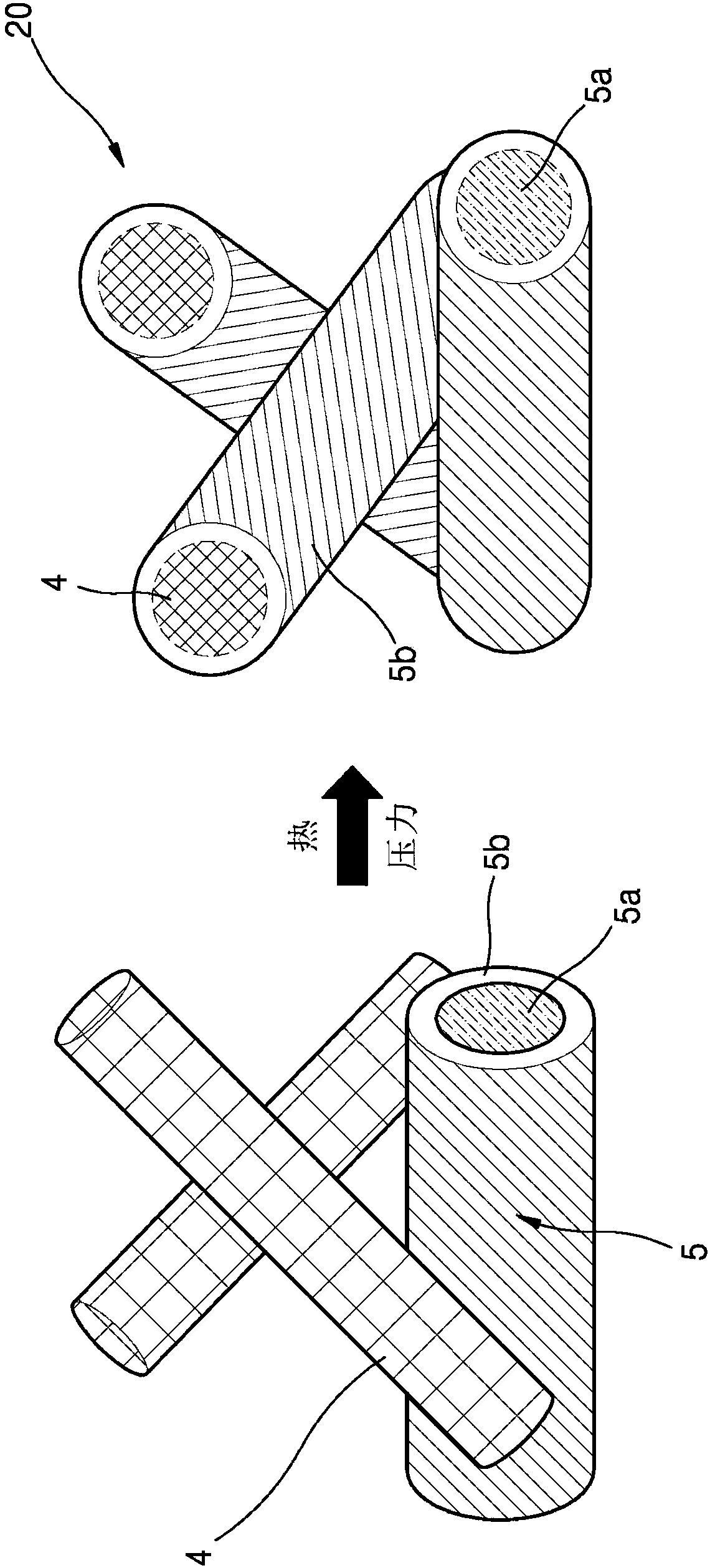
[0143] As the binary polymer fiber, the following fibers were prepared: the polyester core and the low-melting point polyester sheath had a weight ratio of 50:50, a length of 5 mm in order to ensure water dispersibility, and 4 denier (about 20μm cross-sectional diameter) thickness. Glass fibers having a cross-sectional diameter of 13 μm and coated in a manner suitable for water-based dispersion were cut to a length of 13 mm to prepare glass fibers. After blending 40 parts by weight of the above-mentioned glass fiber and 60 parts by weight of the above-mentioned binary polymer fiber, it was stirred in an aqueous solution adjusted to pH 2 with hydrochloric acid for 1 hour. In this case, the total fiber content of glass fibers and binary polymer fibers was adjusted to 2 g per 1 L of water. On the aqueous slurry that has been subjected to the stirring process in the manner described above, a wet papermaking process was performed in a headbox by vacuum suction to form a web. Afte...

Embodiment 2

[0145] In order to improve the binding force between the polyester resin, the glass fiber with special silane coating treatment on the surface was used instead of the glass fiber used in Example 1. After the composite material sheet is produced in the same way, then, the composite material preformed plate is formed in the same method as in Example 1, and then the above-mentioned composite material is preheated in an IR oven at a temperature of 200° C. for 2 minutes. The material preformed sheet expands and is transferred to the press process at room temperature, and pressure is applied to complete the vehicle underbody cover with an average thickness of 2.0 mm.

Embodiment 3

[0147] With 10 parts by weight of the glass fibers used in Example 2 with a special silane-coated surface and 90 parts by weight of binary polymer fibers, except for this point, in the same manner as in Example 2 Method After the composite material sheet is manufactured, the composite material preformed plate is formed in the same method as in Example 2, and then the above composite material is preheated again in an IR oven at a temperature of 200° C. for 2 minutes. The molded sheet expands and is transferred to a press process at room temperature, and pressure is applied to complete the vehicle undercover with an average thickness of 2.0 mm.


PUM

PropertyMeasurementUnit
Lengthaaaaaaaaaa
Melting pointaaaaaaaaaa

Abstract

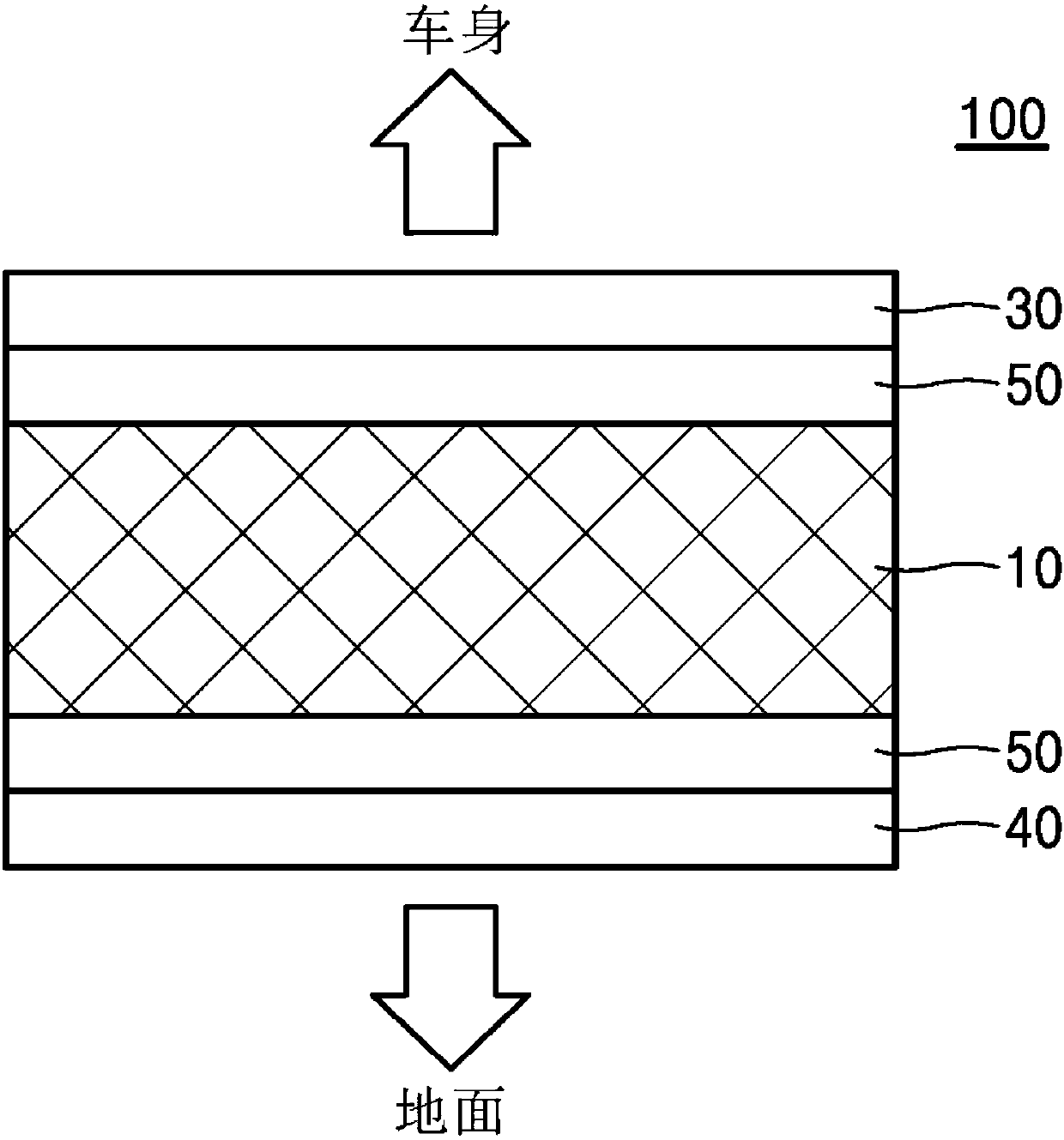
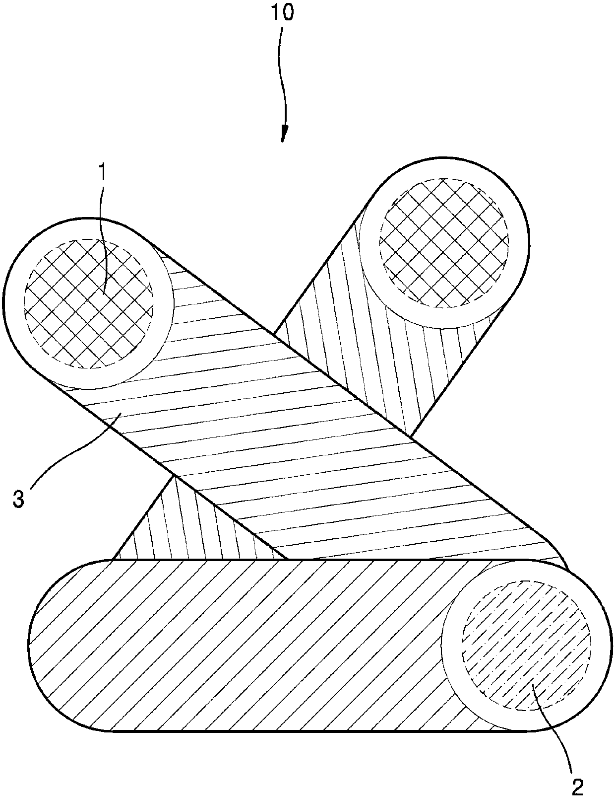
Provided is a vehicle underbody cover comprising: a central layer; and coating layers arranged on both surfaces of the central layer, wherein the central layer comprises: first fibrous particles; second fibrous particles; and a binding material for binding the first fibrous particles and the second fibrous particles, wherein the first fibrous particles and the second fibrous particles are bound bythe binding material so as to form an irregular network structure including pores. The first fibrous particles are inorganic fiber or organic fiber, the second fibrous particles include a first thermoplastic resin, the binding material includes a second thermoplastic resin, and a melting point of the first thermoplastic resin is higher than a melting point of the second thermoplastic resin.

Description

technical field [0001] The present invention relates to an undercover for a vehicle and a manufacturing method thereof. Background technique [0002] The undercover for vehicles has the effect of protecting the vehicle body from external impacts, reducing noise, and improving fuel economy by allowing air to flow smoothly while the vehicle is running. Therefore, it is used not only for commercial vehicles but also for passenger cars due to exhibiting excellent effects in characteristics that are currently prioritized for vehicles such as high fuel economy or quietness. Initially, the vehicle underbody cover was made of steel for the main purpose of protecting the vehicle body, but due to the disadvantages of corrosion and heavy weight, it was gradually replaced by thermoplastic injection molding. However, since thermoplastics exhibit very low physical properties compared to the strength required for undercovers for general vehicles, composite materials in which thermoplastic...

Claims


Application Information

Patent Timeline
IPC IPC(8): B62D25/20B60R13/08B29C43/18
CPCB60R13/0861B29C43/18B29L2031/3005B62D25/20B60R13/08B32B5/06B32B3/26B32B5/022B32B7/12B32B5/26B32B27/08B32B27/12B32B15/14B32B15/08B32B15/04B32B15/20B32B27/36B32B27/32B32B27/302B32B27/365B32B27/34B32B27/304B32B27/40B32B27/308B32B27/322B32B2262/101B32B2262/0269B32B2262/106B32B2262/10B32B2262/103B32B2262/14B32B2260/023B32B2260/046B32B2262/0284B32B2307/72B32B2307/718B32B2307/732B32B2307/546B32B2307/54B32B2307/558B32B2307/306B32B2307/728B32B2307/73B32B2307/3065B32B2605/08
Inventor 安承贤韩庆锡郑胜文
Owner LG HAUSYS LTD
Learn More