Image processing method for air mouse, air mouse and system
An air mouse and image processing technology, applied in electrical digital data processing, data processing input/output process, instruments, etc., can solve the problem that there is no way to increase the moving length of the cursor, etc., to achieve the effect of increasing the moving length
- Summary
- Abstract
- Description
- Claims
- Application Information
AI Technical Summary
Problems solved by technology
Method used
Image
Examples
Embodiment 1
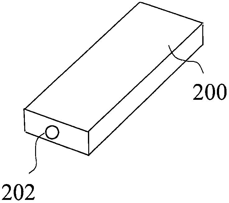
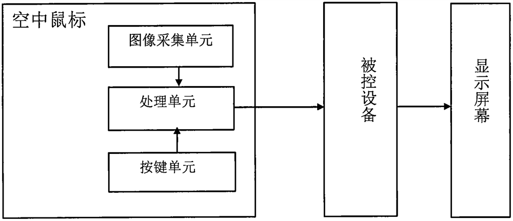
[0067] This embodiment provides an air mouse. like figure 1 As shown, the air mouse includes a casing 200 , a lens 202 disposed in the middle position of the front end of the casing 200 , and a circuit part in the casing 200 . The circuit part includes an image sensor module and a processing unit connected to the lens 202 .
[0068] The lens 202 and the image sensor module together form an image acquisition unit, wherein the lens 202 is a filter lens, capable of filtering out visible light and allowing only infrared light to pass through. The image sensor module is an OV7620 image sensor module, which integrates a CMOS image sensor and a DSP chip, and forms a complete infrared digital camera module with the lens 202, which can capture infrared light-emitting objects and output digital images.
[0069] The processing unit selects the STM32F407 chip of STMicroelectronics, and the output end of the OV7620 image sensor module is electrically connected to the input pin of the STM...
Embodiment 2
[0177] This embodiment provides an air mouse, which can simultaneously increase the moving length of the cursor in the horizontal and vertical directions.
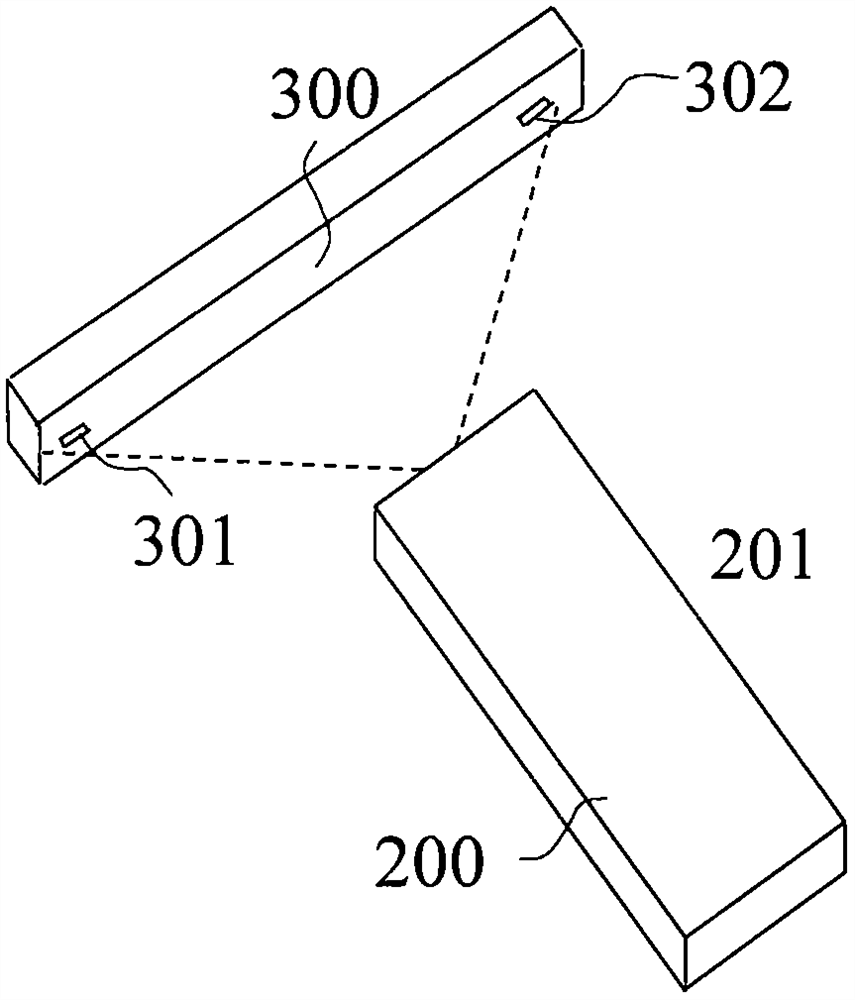
[0178] To achieve this, at least two infrared light sources are required as references. On a rectangular board with a length of 25CM and a height of 15CM, an infrared light-emitting diode is placed in the upper left corner and the lower right corner. The two infrared light-emitting diodes have different brightness, and the image formed in the positioning image has different pixel values. For example, the image formed by the infrared light emitting diode in the upper left corner has a pixel value of 50 for each constituent pixel, and the image formed by the infrared light emitting diode in the lower right corner has a pixel value of 100 for each constituent pixel.
[0179] The difference between the air mouse of this embodiment and the one recorded in Embodiment 1 lies in the processing method of the positioning image by t...
Embodiment 3
[0192] This embodiment provides an air mouse. Compared with the first embodiment, step 1 of the image processing method adopted by the processing unit is different.
[0193] The air mouse of this embodiment and two light sources with different light emitting areas form an air mouse system.
[0194] The two light sources in this embodiment have different light-emitting areas, and the implementations of the two light sources are as follows Figure 9 As shown, there is a small light source 303 on the left edge of the front of the rectangular support 300, and a large light source 304 on the right edge. The light-emitting area of the small light source 303 is 2 square millimeters, and the light-emitting area of the large light source 304 is 4 square millimeters. There are infrared light-emitting diodes between the two light sources, and the distance between them is 20 cm.
[0195] The images formed by the two infrared light sources in the positioning image are composed of dif...
PUM
| Property | Measurement | Unit |
|---|---|---|
| Light emitting area | aaaaa | aaaaa |
| Light emitting area | aaaaa | aaaaa |
Abstract
Description
Claims
Application Information
 - R&D
- Intellectual Property
- Life Sciences
- Materials
- Tech Scout
- Unparalleled Data Quality
- Higher Quality Content
- 60% Fewer Hallucinations
Browse by: Latest US Patents, China's latest patents, Technical Efficacy Thesaurus, Application Domain, Technology Topic, Popular Technical Reports.
© 2025 PatSnap. All rights reserved.Legal|Privacy policy|Modern Slavery Act Transparency Statement|Sitemap|About US| Contact US: help@patsnap.com


