Lifting type compact shelf

A compact rack, lift-type technology, applied in the field of compact racks, can solve the problems of easy dust accumulation, small floor space, large floor space, etc., to achieve the effect of reducing space

Pending Publication Date: 2022-07-22
JIANGXI SUNSHINE SAFETY EQUIP GRP CO LTD
View PDF1 Cites 1 Cited by
  • Summary
  • Abstract
  • Description
  • Claims
  • Application Information

AI Technical Summary

Problems solved by technology

[0005] In order to overcome the shortcomings of the existing multi-functional compact racks that are open and easy to accumulate dust, and the rack body is relatively large and occupies a large area, the technical problem is to provide a compact rack that is installed underground, has a small footprint, and has a sealing High-performance, and liftable compact racks that can be lifted

Method used


Image

  • Lifting type compact shelf
  • Lifting type compact shelf
  • Lifting type compact shelf

Examples


Embodiment 1

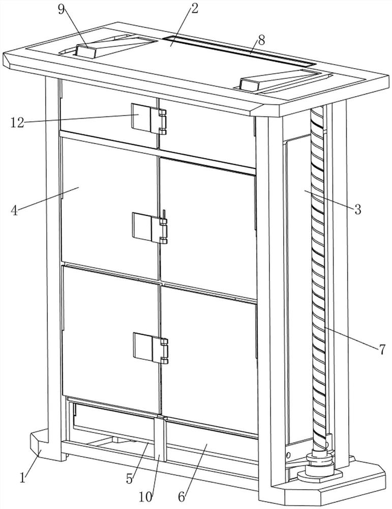
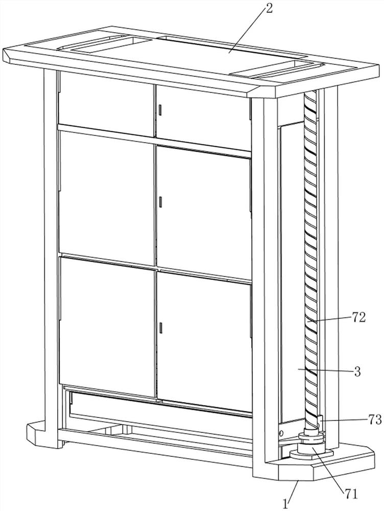
[0035] A lift-type compact rack, such as Figure 1-2 As shown, it includes a supporting slide rail 1, a cabinet 2, a slider 3, a first rotating plate 4, a storage box 5, a second rotating plate 6, a lifting mechanism 7 and a prompting mechanism 8, and the left and right sides of the supporting slide rail 1 are The sliding connection is provided with a slider 3, and a cabinet 2 is arranged between the sliders 3. The cabinet 2 is used for storing items. There are three cavities on the left and right sides of the cabinet 2 respectively. A rotating plate 4, the first rotating plate 4 can cover the front side of the cavity of the cabinet 2, a storage box 5 is slidably connected to the lower part of the cabinet 2, and a second rotating plate 6 is rotatably connected to the left front side of the storage box 5. The two rotating plates 6 are used to cover the front side of the storage box 5 , a lifting mechanism 7 is provided between the support slide rail 1 and the slider 3 to drive ...

Embodiment 2

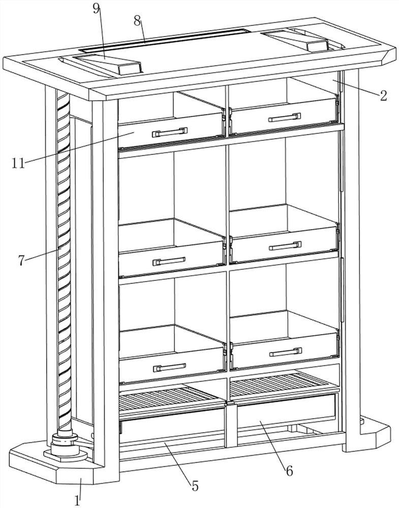
[0040] On the basis of Example 1, as figure 1 , figure 2 , Figure 7 and Figure 8 As shown, it also includes a display mechanism 9, which can display the items placed in the cabinet 2. The display mechanism 9 includes a third rotating plate 91, a first sliding plate 92, a second telescopic spring 93, a second rotating shaft 94, and a torsion spring. 95 and the cam 96, the left and right sides of the top rear side of the cabinet 2 are rotatably connected with the third rotating plate 91, and the third rotating plate 91 is slidably connected with the first sliding plate 92, and the first sliding plate 92 can be in the first sliding plate 92. The three rotating plates 91 slide inside, and a second telescopic spring 93 is provided between the top of the first sliding plate 92 and the third rotating plate 91. Under the action of the second telescopic spring 93, the first sliding plate 92 can be driven to move and reset. , the left and right sides of the upper part of the cabin...


PUM


Abstract

The invention relates to a compact shelf, in particular to a lifting type compact shelf. The technical problem is to provide the lifting type compact shelf which is installed underground, occupies a small area, has sealing performance and can be lifted. According to the technical scheme, the lifting type compact shelf comprises a supporting sliding rail, a cabinet, sliding blocks, first rotating plates, a storage box and the like, the sliding blocks are arranged on the left side and the right side in the supporting sliding rail in a sliding mode, the cabinet is arranged between the sliding blocks, the left side and the right side of the cabinet are each provided with three cavities, and the three first rotating plates are arranged on the left side and the right side of the front portion of the cabinet in a rotating mode; and a storage box is slidably arranged at the lower part in the cabinet. The output shaft of the motor is remotely controlled to rotate, so that the screw rod drives the sliding block and the cabinet to rise upwards, and then a user can take articles conveniently.

Description

technical field [0001] The invention relates to a compact rack, in particular to a lift-type compact rack. Background technique [0002] Compact racks are widely used, such as libraries, hospitals and schools, where compact racks are usually used to store some more important documents and items. Existing compact racks generally adopt the structure of bookshelves, which are generally fixed and more troublesome to use. [0003] Patent Publication No. CN215382304U A multifunctional compact rack, comprising: at least one rack body, a slide rail and a motor; the slide rail includes a first slide rail and a second slide rail, the first slide rail is installed on the ground, The second slide rail is installed on a wall perpendicular to the ground; the frame body can slide back and forth on the first slide rail and the second slide rail under the drive of the motor; the frame body includes multiple Each of the storage compartments includes a base, a barbed tooth plate, a positionin...

Claims


Application Information

Patent Timeline
IPC IPC(8): A47B51/00A47B63/00A47B96/00
CPCA47B51/00A47B63/00A47B96/00
Inventor 张菲菲
Owner JIANGXI SUNSHINE SAFETY EQUIP GRP CO LTD
Why Eureka
Try Eureka