Novel infusion apparatus
An infusion set and a new type of technology, applied in the field of infusion sets, can solve the problem of inability to achieve one-time intravenous injection of medicinal liquid, and achieve the effect of maintaining a stable infusion speed
- Summary
- Abstract
- Description
- Claims
- Application Information
AI Technical Summary
Problems solved by technology
Method used
Image
Examples
Embodiment 1
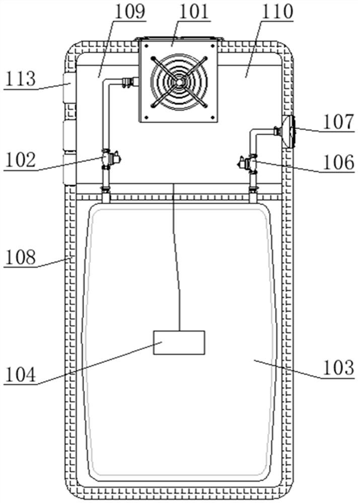
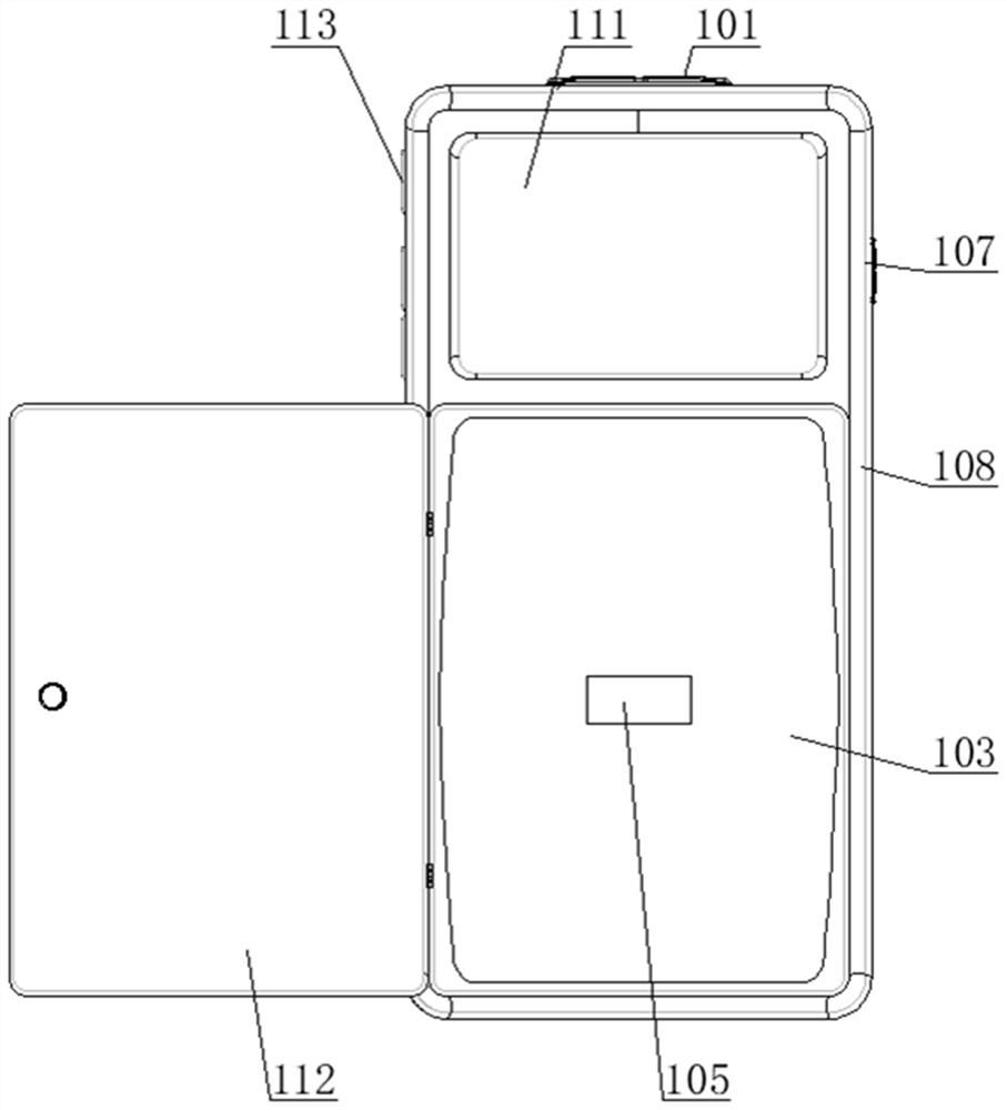
[0035] like Figure 1-10As shown, a new type of infusion set includes a pressurizing mechanism 1, a liquid mixing mechanism 2 and a shut-off joint 3. The liquid mixing mechanism 2 includes a liquid mixing pipe 201 and a thimble 202 symmetrically distributed at the end of the mixing pipe 201. The liquid mixing pipe 201 and the thimble 202 It is connected by a hose, and the outside of the hose connecting the liquid mixing pipe 201 and the thimble 202 located on the lower side is provided with a water stop clip 203, and a floating ball 204 is provided inside the liquid mixing pipe 201. The upper left and right sides of the liquid mixing pipe 201 A vent hole 205 and a first heparin cap 206 are provided, respectively.
[0036] The pressurizing mechanism 1 includes a micro air pump 101 and an intake valve 102. The output end of the micro air pump 101 is connected to the intake valve 102 through a conduit, and the output end of the intake valve 102 is connected to an air bag 103 thro...
Embodiment 2
[0040] like Figure 1-10 As shown, a new type of infusion set includes a pressurizing mechanism 1, a liquid mixing mechanism 2 and a shut-off joint 3. The liquid mixing mechanism 2 includes a liquid mixing pipe 201 and a thimble 202 symmetrically distributed at the end of the mixing pipe 201. The liquid mixing pipe 201 and the thimble 202 It is connected by a hose, and the outside of the hose connecting the liquid mixing pipe 201 and the thimble 202 located on the lower side is provided with a water stop clip 203, and a floating ball 204 is provided inside the liquid mixing pipe 201. The upper left and right sides of the liquid mixing pipe 201 A vent hole 205 and a first heparin cap 206 are provided, respectively.
[0041] The liquid mixing pipe 201 is arranged in a cylindrical shape, and the inner upper and lower end surfaces of the mixing pipe 201 are arranged in a circular arc shape.
[0042] The pressurizing mechanism 1 includes a micro air pump 101 and an intake valve 10...
Embodiment 3
[0046] like Figure 1-10 As shown, a new type of infusion set includes a pressurizing mechanism 1, a liquid mixing mechanism 2 and a shut-off joint 3. The liquid mixing mechanism 2 includes a liquid mixing pipe 201 and a thimble 202 symmetrically distributed at the end of the mixing pipe 201. The liquid mixing pipe 201 and the thimble 202 It is connected by a hose, and the outside of the hose connecting the liquid mixing pipe 201 and the thimble 202 located on the lower side is provided with a water stop clip 203, and a floating ball 204 is provided inside the liquid mixing pipe 201. The upper left and right sides of the liquid mixing pipe 201 A vent hole 205 and a first heparin cap 206 are provided, respectively.
[0047] The liquid mixing pipe 201 is arranged in a cylindrical shape, and the inner upper and lower end surfaces of the mixing pipe 201 are arranged in a circular arc shape.
[0048] The pressurizing mechanism 1 includes a micro air pump 101 and an intake valve 10...
PUM
 Abstract
Description
Claims
Application Information
 - R&D
- Intellectual Property
- Life Sciences
- Materials
- Tech Scout
- Unparalleled Data Quality
- Higher Quality Content
- 60% Fewer Hallucinations
Browse by: Latest US Patents, China's latest patents, Technical Efficacy Thesaurus, Application Domain, Technology Topic, Popular Technical Reports.
© 2025 PatSnap. All rights reserved.Legal|Privacy policy|Modern Slavery Act Transparency Statement|Sitemap|About US| Contact US: help@patsnap.com


