Stirring device for chemical industry

A stirring device, chemical technology

Pending Publication Date: 2022-07-22
北京中科金源环保科技有限公司
View PDF0 Cites 0 Cited by
  • Summary
  • Abstract
  • Description
  • Claims
  • Application Information

AI Technical Summary

Problems solved by technology

[0002] Chemical materials need to be mixed and stirred with a mixer. The existing mixing equipment and the stirring paddles are all installed in a fixed position, which causes the paddles to form a laminar flow when mixing the materials, resulting in uneven mixing of the materials, and when adding powder When the powdery material floats on the upper layer, it cannot quickly enter the solution, which reduces the stirring speed, and in the process of high-speed stirring, a large amount of heat will be generated to cool down, and the inner wall of the cylinder is often not stirred. Wherever you go, you can only rely on the liquid flow to drive the stirring

Method used


Image

  • Stirring device for chemical industry
  • Stirring device for chemical industry
  • Stirring device for chemical industry

Examples


specific Embodiment approach 1

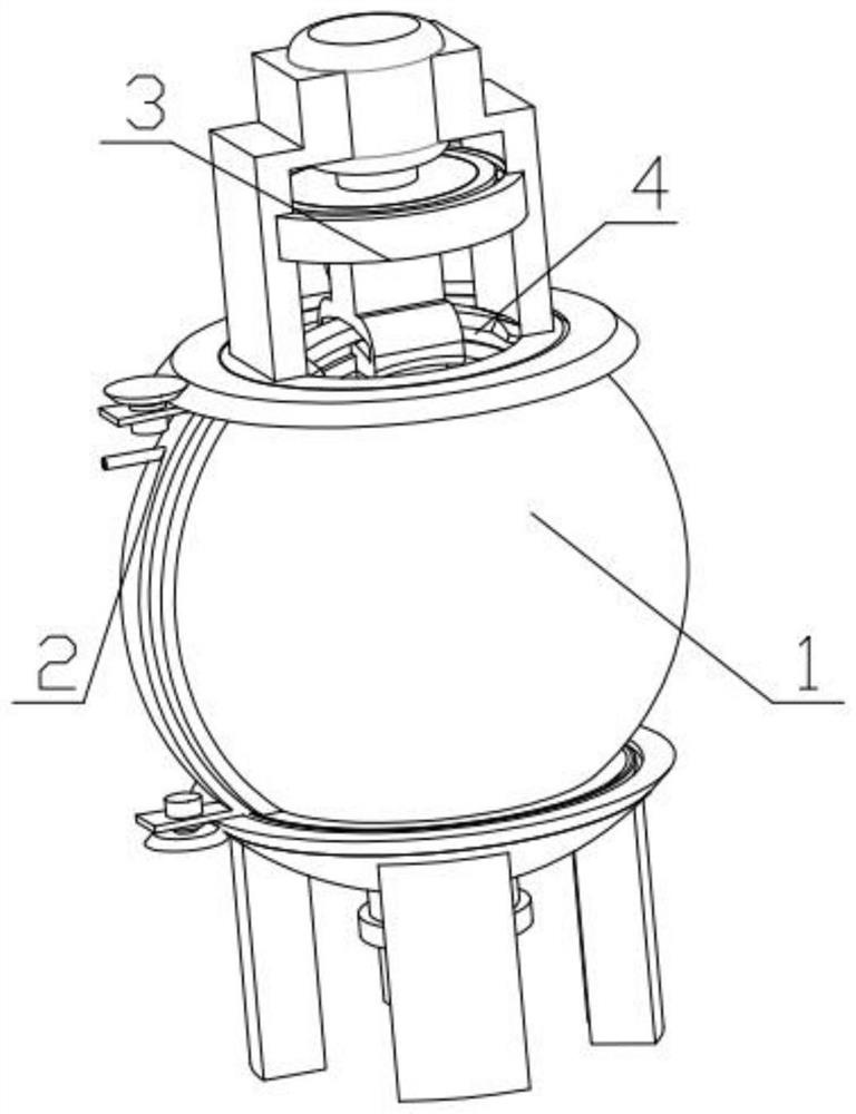
[0027] Combine below Figure 1-8 Illustrating this embodiment, a chemical stirring device includes a cylinder 1, a cooling mechanism 2, a power mechanism 3 and a stirring mechanism 4. The cooling mechanism 2 is slidably installed in a groove provided on the cylinder 1, and the cylinder 1 is screwed with the cooling mechanism 2, the power mechanism 3 is fixedly installed on the cylinder body 1, the stirring mechanism 4 is slidably installed in the groove set on the power mechanism 3, and the stirring mechanism 4 is engaged with the power mechanism 3.

specific Embodiment approach 2

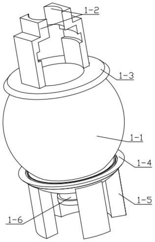
[0028] Combine below Figure 1-8 This embodiment will be described. This embodiment will further describe the first embodiment. The cylinder block 1 includes a circular cylinder block 1-1, a top mounting frame 1-2, an upper helical gear ring 1-3, and a lower helical gear ring 1. -4. Support legs 1-5, bottom discharge pipe 1-6, support legs 1-5 are fixedly installed on the circular cylinder body 1-1, and bottom discharge pipe 1 is fixedly installed on the circular cylinder body 1-1 -6, the upper helical gear ring 1-3 is fixed on the circular cylinder block 1-1, the lower helical gear ring 1-4 is fixed on the circular cylinder block 1-1, and the circular cylinder block 1-1 is fixed on the Top mount brackets 1-2 are installed.

specific Embodiment approach 3

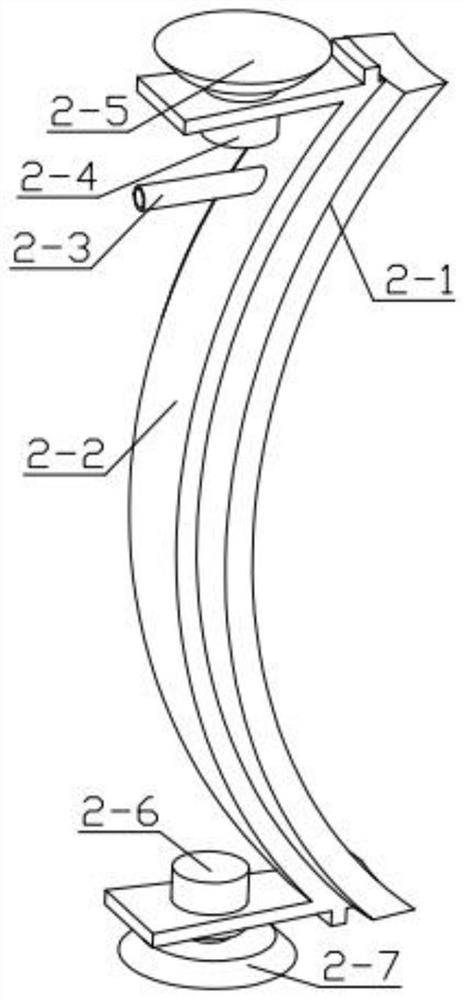
[0029] Combine below Figure 1-8 This embodiment will be described. This embodiment will further describe the second embodiment. The cooling mechanism 2 includes a wiping sea noodle strip 2-1, an arc top plate 2-2, a water inlet pipe 2-3, an upper motor 2-4, an upward slope Gear 2-5, lower motor 2-6, lower helical gear 2-7, a water inlet pipe 2-3 is fixedly installed in the groove set on the arc top plate 2-2, and the water outlet of the water inlet pipe 2-3 is used to wipe the sea noodles 2-1 contact, wipe the sea noodles 2-1 is fixedly installed on the arc top plate 2-2, the arc top plate 2-2 is slidably installed in the groove set on the upper helical gear ring 1-3, and the arc top plate 2-2 slides Installed in the groove set on the lower helical gear ring 1-4, the upper motor 2-4 is fixedly installed on the arc top plate 2-2, the output end of the upper motor 2-4 is fixedly installed with the upper helical gear 2-5, Gear 2-5 meshes with upper helical gear ring 1-3, lower ...


PUM


Abstract

The invention relates to a related device for chemical engineering, in particular to a stirring device for chemical engineering, which comprises a cylinder body, a cooling mechanism, a power mechanism and a stirring mechanism, the cooling mechanism is slidably installed in a groove arranged on the cylinder body, the cylinder body is in threaded connection with the cooling mechanism, the power mechanism is fixedly installed on the cylinder body, and the stirring mechanism is fixedly installed on the cylinder body. The stirring mechanism is mounted in a groove formed in the power mechanism in a sliding manner, and the stirring mechanism is meshed with the power mechanism; according to the device, vortexes of different sizes can be formed for stirring, various stirring requirements are met, newly-added powdery materials can be rapidly fed into the middle position of liquid, material mixing is accelerated, the dust phenomenon of a material adding opening is avoided, the liquid near the inner wall of the cylinder body can be kept to flow all the time, the uniform mixing speed is increased, and the stirring efficiency is improved. And meanwhile, the device can perform cooling treatment.

Description

technical field [0001] The invention relates to a chemical related device, in particular to a chemical stirring device. Background technique [0002] Chemical materials need to be mixed and stirred with a mixer. The existing stirring equipment and stirring paddles are installed in fixed positions, which leads to laminar flow when the stirring paddles mix materials, resulting in uneven stirring of materials, and when adding powder When the powdery material floats in the upper layer, it cannot quickly enter the solution, which reduces the stirring speed. Moreover, during the high-speed stirring process, a large amount of heat will be generated, which needs to be cooled down, and the inner wall of the cylinder is often not stirred. To the place, only rely on the liquid flow to drive the stirring. SUMMARY OF THE INVENTION [0003] The main technical problem to be solved by the present invention is to provide a chemical stirring device. The device can form vortices of differen...

Claims


Application Information

Patent Timeline
Patent Type & Authority Applications(China)
IPC IPC(8): B01F27/95B01F27/11B01F27/091B01F35/30B01F35/92
Inventor 曹玉宝
Owner 北京中科金源环保科技有限公司
Why Eureka
Try Eureka