

Universal rotary table box body structure for numerical control rotary table and horizontal machine tool
A box structure and machine tool technology, applied to metal processing machinery parts, metal processing equipment, manufacturing tools, etc., to achieve the effects of ensuring firmness, saving cleaning time, and improving versatility
- Summary
- Abstract
- Description
- Claims
- Application Information
AI Technical Summary
Problems solved by technology
Method used
Image

Examples
Embodiment 1
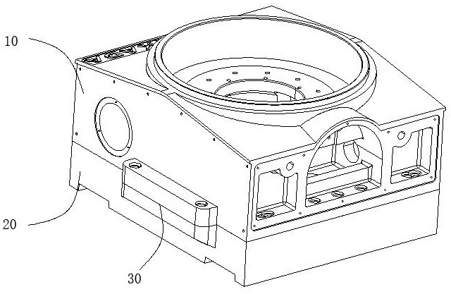
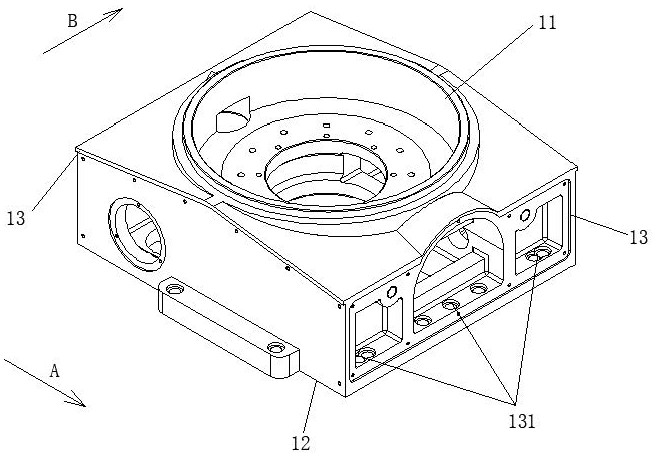
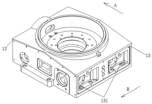
[0058] like Figure 1 to Figure 10 The shown CNC turntable and the general turntable box structure of the horizontal machine tool include: a shell 10, a connecting seat 20 and a bump 30;
[0059] The housing 10 includes an upper dome surface 11 , a lower bottom surface 12 and a side elevation 13 extending upward along the outer edge of the lower bottom surface 12 , and two opposite side elevations 13 along the first horizontal direction A are respectively provided. The first cavity and the second cavity, the first installation part 131 connected to the horizontal milling machine is embedded in the first cavity and the second cavity;
[0060] The connecting seat 20 is detachably installed under the casing 10, and includes an upper connecting surface arranged opposite to the lower bottom surface 12, and a lower connecting surface arranged opposite to the machine tool table, and a connection with the horizontal machining center is located on the lower connecting surface. the sec...
Embodiment 2
[0073] The difference from Example 1 is that, as Figure 11-17 As shown, the upper calibration block 31 and the lower calibration block 32 are arranged on both sides of the contact surface of the housing 10 and the connecting seat 20, and the structure of the guiding and positioning mechanism 60 is the same, and the rest of the structure is the same, and will not be repeated here.
[0074] When there is an installation gap between the upper calibration block 31 and the lower calibration block 32, in order to ensure the accuracy of installation and positioning, the guide positioning mechanism 60 includes a guide shaft 61a, and a limit rod 62a slidably arranged in the inner hole of the guide shaft 61a; the guide shaft 61a is fixed on the lower calibration block 32, and its end extending toward the housing 10 is provided with a conical annular surface 611a matched with the positioning hole of the upper calibration block 31, and the inner hole is provided with a sliding groove for ...
PUM
 Abstract
Description
Claims
Application Information