Rotary electric vehicle hub cooling manipulator

An electric vehicle and rotary technology, applied in the direction of manipulators, electric vehicles, motors, etc., can solve the problems of high labor intensity, inability to transfer immediately, and easy burns, so as to avoid cumbersomeness and hidden dangers, reduce impact, and avoid The effect of manual picking

Active Publication Date: 2022-07-22
JIANGSU JUN SUPER ELECTRIC CAR ACCESSORIES MFG
View PDF10 Cites 1 Cited by
  • Summary
  • Abstract
  • Description
  • Claims
  • Application Information

AI Technical Summary

Problems solved by technology

[0002] In the production process of the wheel hub, because the temperature of the aluminum wheel hub that has just been cast is very high, it cannot be transferred to the next process for processing immediately. In order to save time and improve production efficiency, the newly cast wheel hub can be transferred to the next process as soon as possible. To forcibly lower the temperature of the wheel, most of the aluminum alloy wheel manufacturers currently use water cooling to cool down, that is, the operator clamps the wheel with pliers and puts the wheel in the water tank to cool down, and then manually takes the wheel out of the water , this method of completely relying on manual work not only has low production efficiency, but also has high labor intensity for workers, and is prone to burn accidents

Method used


Image

  • Rotary electric vehicle hub cooling manipulator
  • Rotary electric vehicle hub cooling manipulator
  • Rotary electric vehicle hub cooling manipulator

Examples


Embodiment 1

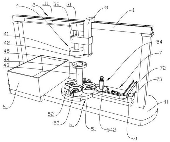
[0031] Example 1: as Figure 1 to Figure 11 As shown, the present invention provides a rotary electric wheel hub cooling manipulator, including a fixed frame 1, the top of the fixed frame 1 is connected with a walking frame 3 through a driving mechanism 2, and a lifting cylinder 31 is fixed on the walking frame 3. 3. The sliding sleeve at one end away from the fixed frame 1 is provided with a sliding seat 32. The sliding seat 32 is fixedly connected with the piston rod of the lifting cylinder 31. The sliding seat 32 is adsorbed by a lifting electromagnet 4 with a cooling placing frame 5. The cooling placing frame 5 includes The disc seat 51 is placed, and several hub placement bins 52 are evenly distributed along the circumferential direction on the disc seat 51. The bottom of the fixing frame 1 is provided with a bottom plate 11, and the bottom plate 11 is sequentially provided with a cooling water tank 6, an arc limit groove 53 and an upper and lower plate. The feeding devic...

Embodiment 2

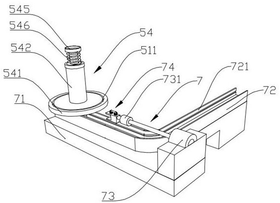
[0036] Embodiment 2: On the basis of Embodiment 1, as Figure 1 to Figure 4 and Figures 6 to 8 As shown, the wheel hub placement rack 54 includes a support plate 541, an L-shaped chute 721 is provided on the L-shaped conveying track 72, the top surface of the L-shaped chute 721 is flush with the top surface of the silo body 521, and the support plate 541 is slidably arranged on the On the top surface of the L-shaped chute 721, the width of the L-shaped chute 721 is the same as the distance between the first support plate 5231 and the second support plate 5232. The support plate 541 is fixedly provided with a support column 542. The support column 542 One end of the support column 542 is located in the L-shaped chute 721, one end of the support column 542 is rotatably sleeved with a positioning ring 543, the other end of the support column 542 is movably provided with a buffer rod 544, and the end of the buffer rod 544 away from the support column 542 is provided with a buffer...

Embodiment 3

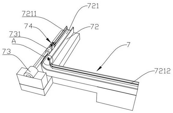
[0040] Embodiment 3: On the basis of Embodiment 1, as Figure 1 to Figure 3 As shown, the opposite inner walls of the L-shaped chute 721 are also provided with a first chute 7211 and a second chute 7212 that communicate with the first guide slot 5233 and the second guide slot 5234 respectively, and the positioning ring 543 is slidably clamped. Between the first chute 7211 and the second chute 7212, when the hub placement frame 54 moves in the L-shaped chute 721, the support plate 541 can be guided by the first guide groove 5233 and the second guide groove 5234. Moving (ie, moving from the L-shaped chute 721 to the wheel hub placement bin 52 ) is beneficial to keep the wheel hub placement frame 54 stable when moving in the L-shaped chute 721 .


PUM


Abstract

The invention discloses a rotary electric vehicle hub cooling manipulator, and relates to the technical field of electric vehicle hub production, the rotary electric vehicle hub cooling manipulator comprises a fixing frame, the top of the fixing frame is connected with a walking frame through a driving mechanism, the walking frame is fixedly provided with a lifting cylinder, and the end, away from the fixing frame, of the walking frame is slidably sleeved with a sliding seat; the sliding seat is fixedly connected with a piston rod of the lifting air cylinder, a cooling placement frame is attracted to the sliding seat through a lifting electromagnet, the cooling placement frame comprises a placement disc seat, a plurality of hub placement bins are evenly distributed on the placement disc seat in the circumferential direction, and a bottom plate is arranged at the bottom of the fixing frame; a cooling water tank, an arc-shaped limiting groove and a feeding and discharging device are sequentially arranged on the bottom plate, and the containing disc base is located in an arc-shaped opening of the arc-shaped limiting groove. The hub cooling device has the advantages that the hub can be automatically grabbed for cooling work, manual clamping and taking work is replaced, and safety and working efficiency are improved.

Description

technical field [0001] The invention relates to the technical field of electric wheel hub production, in particular to a rotary electric wheel hub cooling manipulator. Background technique [0002] In the process of wheel hub production, due to the high temperature of the just-cast aluminum hub blank, it cannot be immediately transferred to the next process for processing. In order to save time and improve production efficiency, the newly-cast aluminum wheel hub is transferred to the next process as soon as possible To forcibly lower the temperature of the wheel hub, at present, most aluminum alloy wheel hub manufacturers use the water cooling method, that is, the operator clamps the wheel hub with hand pliers and puts it into the water tank for cooling, and then manually removes the wheel hub from the water. , This method, which is completely manual, not only has low production efficiency, but also has high labor intensity for workers, and is prone to scalding accidents. ...

Claims


Application Information

Patent Timeline
Patent Type & Authority Applications(China)
IPC IPC(8): B25J11/00B25J19/00
CPCB25J11/00B25J19/00Y02T10/64
Inventor 马俊超毛玉兰
Owner JIANGSU JUN SUPER ELECTRIC CAR ACCESSORIES MFG
Why Eureka
Try Eureka