Dual-motor power system

A power system, dual-motor technology, applied in control devices, vehicle components, transportation and packaging, etc., can solve the problems of low braking energy recovery capacity, poor economy, high noise, etc., to simplify structure and function, reduce noise, etc. , the effect of reducing the axial size

Pending Publication Date: 2022-07-22
GUANGZHOU AUTOMOBILE GROUP CO LTD
View PDF0 Cites 0 Cited by
  • Summary
  • Abstract
  • Description
  • Claims
  • Application Information

AI Technical Summary

Problems solved by technology

However, while the existing dual-motor power system meets the high power requirements, there are problems such as poor economy, low braking energy recovery capability, and high noise in the high speed range.

Method used


Image

  • Dual-motor power system
  • Dual-motor power system
  • Dual-motor power system

Examples


Embodiment 1

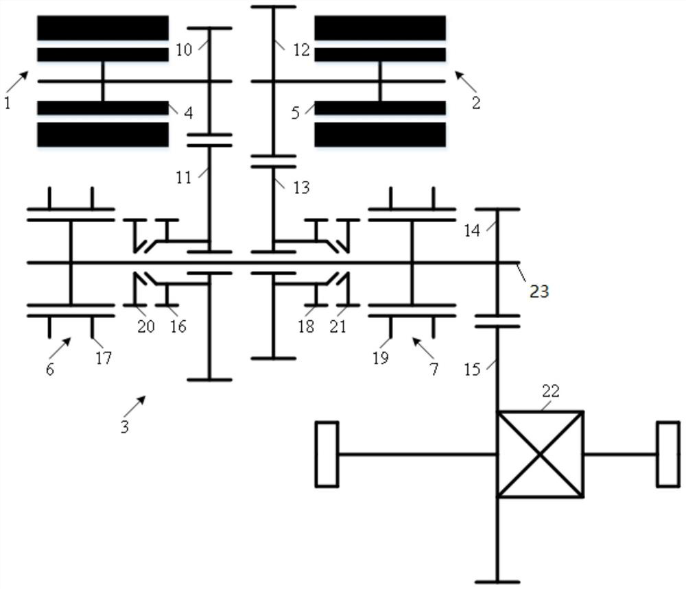
[0030] see figure 1 ,exist figure 1 The general arrangement of an embodiment of the dual-motor power system of the present invention is exemplarily shown in FIG. like figure 1 As shown, the dual motor power system of the present invention includes a first motor 1 , a second motor 2 and a transmission 3 .

[0031] Wherein, the first motor 1 and the second motor 2 are the power sources of the dual-motor power system, and the dual-motor power system of the present invention can be powered by one of the motors or by the two motors at the same time.

[0032] Specifically, the first electric machine 1 has a first rotor 4 . The second electric machine 2 has a second rotor 5 . The transmission 3 has a first controllable torque transmission device 6 , a second controllable torque transmission device 7 , a first fixed shaft gear pair driving gear 10 , a first fixed shaft gear pair driven gear 11 , and a second fixed shaft gear pair The driving gear 12 , the driven gear 13 of the se...

Embodiment 2

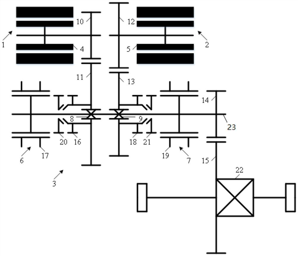
[0041] like figure 2 As shown, the second embodiment is basically the same as the first embodiment, except that the transmission 3 further includes a first one-way clutch 8 and a second one-way clutch 9 . One end of the first one-way clutch 8 is fixedly connected to the driven gear 11 of the first fixed shaft gear pair, and the other end is detachably connected to the transmission shaft 23 . The first fixed shaft gear pair driven gear 11 can transmit the forward output torque of the first motor 1 to the final drive gear 14 through the first one-way clutch 8 , and cannot output the reverse output of the first motor 1 Torque is transmitted to the final drive gear 14 through the first one-way clutch 8 . One end of the second one-way clutch 9 is fixedly connected to the driven gear 13 of the second fixed-shaft gear pair, and the other end is detachably connected to the transmission shaft 23 . The second fixed-shaft gear pair driven gear 13 can transmit the forward output torque...

Embodiment 3

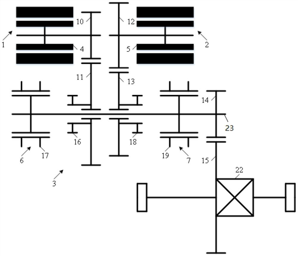
[0045] like image 3 As shown, the third embodiment is basically the same as the first embodiment, the difference is that the first controllable torque transmission device 6 is a claw clutch, which does not have the first lock ring 20; the second controllable torque transmission device 7 is Claw clutch, which does not have the second lock ring 21 .

[0046] Embodiment 3 Compared with Embodiment 1, the first controllable torque transmission device 6 and the second controllable torque transmission device 7 do not have lock rings, and do not rely on friction but on the precision of the first motor 1 and the second motor 2. Speed ​​regulation realizes rotational speed synchronization between the first engagement portion 16 , the second engagement portion 17 , and between the third engagement portion 18 and the second engagement portion 19 , reducing wear and power loss, and reducing shift time .


PUM


Abstract

A dual-motor power system comprises a first motor, a second motor and a transmission, the transmission is provided with a first controllable torque transmission device and a second controllable torque transmission device, the first motor is connected with a wheel through a first transmission path, and the second motor is connected with the wheel through a second transmission path. The first controllable torque transmission device can be controllably switched between a joint position and a separation position, when the first controllable torque transmission device is located at the joint position, the first transmission path is conducted, and when the first controllable torque transmission device is located at the separation position, the first transmission path is interrupted; the second controllable torque transmission device can be controllably switched between a joint position and a separation position, when the second controllable torque transmission device is located at the joint position, the second transmission path is conducted, and when the second controllable torque transmission device is located at the separation position, the second transmission path is interrupted.

Description

technical field [0001] The invention relates to the technical field of automobiles, in particular to a dual-motor power system. Background technique [0002] In the field of pure electric vehicle drive technology, the single-motor single-speed power system is the current mainstream; and due to the needs of both power and economy, the single-motor multi-speed power system has become a research and development hotspot, especially the single-motor two-speed power system. for the most. However, no matter whether it can realize the power uninterrupted shifting, the single-motor two-speed power system usually requires a larger gear ratio (speed ratio of the two gears), so that the speed difference between the two ends of the shifting element is larger when shifting. , resulting in increased difficulty in shifting, prolonged power interruption or serious wear of shifting elements. Therefore, the single-motor two-speed power system is very limited in the application of pure electr...

Claims


Application Information

Patent Timeline
Patent Type & Authority Applications(China)
IPC IPC(8): B60K17/08
CPCB60K17/08
Inventor 陈志峰董泽庆祖国强黄秀成章佳文尚阳朱旭张安伟
Owner GUANGZHOU AUTOMOBILE GROUP CO LTD
Why Eureka
Try Eureka