Protective isolation fence and processing method thereof

A technology of protection isolation and togetherness, applied to wire processing, other household appliances, building types, etc., can solve the problems of lack of protection, no protection, damage, etc., achieve good protection, enhance strength, and avoid attacks. Effect

Pending Publication Date: 2022-07-22
北京市中凯路达交通技术有限责任公司
View PDF10 Cites 0 Cited by
  • Summary
  • Abstract
  • Description
  • Claims
  • Application Information

AI Technical Summary

Problems solved by technology

At present, the barriers only play the role of isolation and have no protective ability. The reason is that the mesh of the barrier is flat, so it can only function as isolation for general animal intrusion, but cannot provide protection. function, if the isolation barrier is attacked, it is also easy to cause damage

Method used


Image

  • Protective isolation fence and processing method thereof
  • Protective isolation fence and processing method thereof
  • Protective isolation fence and processing method thereof

Examples


Embodiment 1

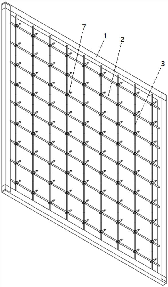
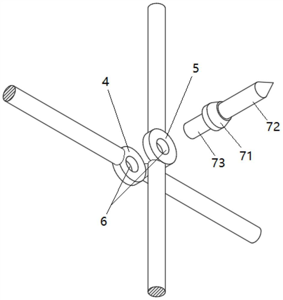
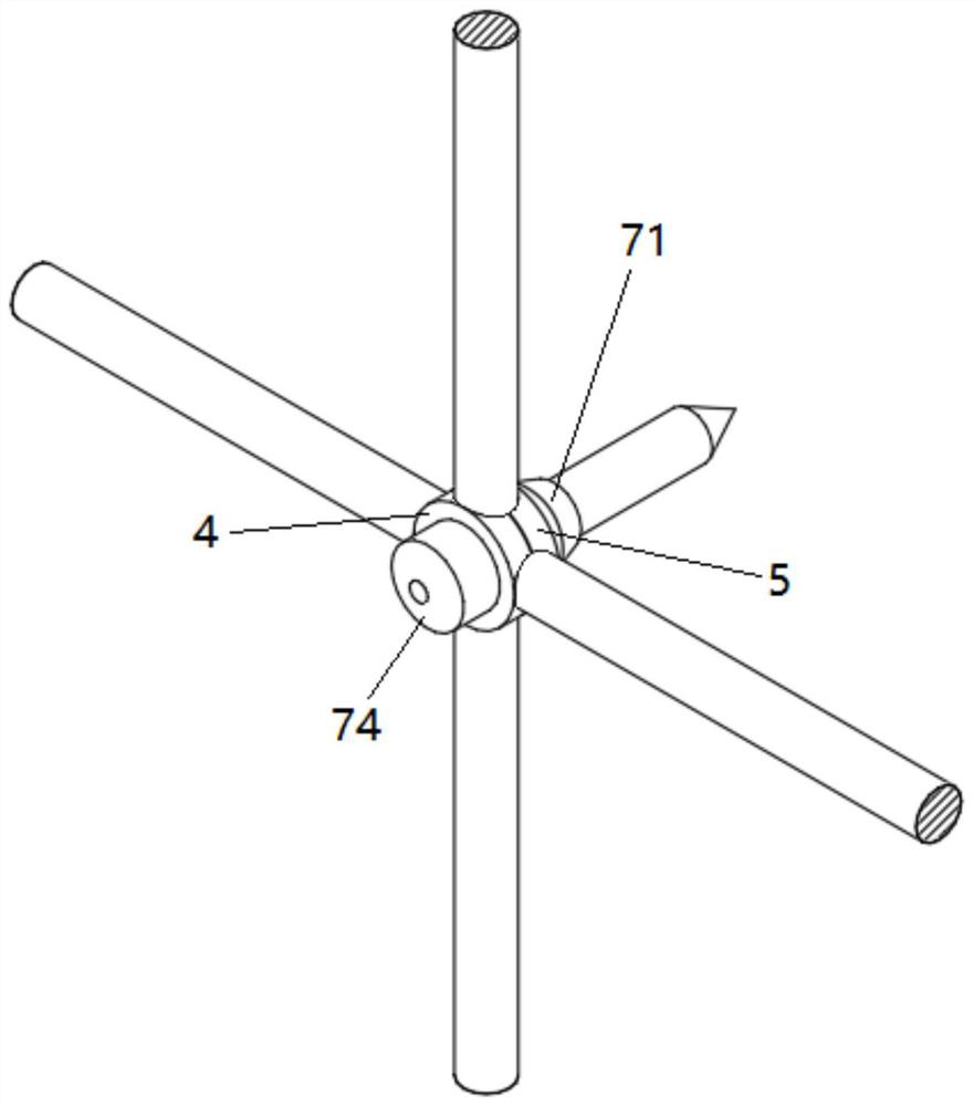
[0028] see Figure 1-3 , the present embodiment provides a protective isolation grille, including an outer frame 1 and a mesh fixed inside the outer frame, and the mesh includes a number of transverse reinforcement bars 2 and a number of longitudinal reinforcement bars 3 arranged in an intersecting manner. A first flat portion 4 and a second flat portion 5 are respectively formed at the intersecting portion of the steel bar and each longitudinal steel bar by punching, and the first flat portion 4 and the second flat portion 5 are provided with through holes 6 that communicate with each other. The barbed nails 7 penetrate through the through holes and extend out, and the first flat part 4 and the second flat part 5 are pressed together by riveting, so that several transverse steel bars 2 and several longitudinal steel bars 3 are fixedly connected.

[0029] In this embodiment, the inner edges of the four sides of the outer frame 1 are provided with a number of insertion holes (n...

Embodiment 2

[0037] see Figure 1-3 , this embodiment provides a processing method for a protective isolation barrier, which specifically includes the following steps:

[0038] S1. Use a stamping die to punch the intersecting parts of each transverse steel bar and each longitudinal steel bar to form the first flat part 4 and the second flat part 5 respectively, and at the same time, in the first flat part 4 and the second flat part 5 Through holes 6 are formed on both;

[0039] S2. Arrange several transverse reinforcing bars 2 and several longitudinal reinforcing bars 3 in an intersecting manner, so that the first flat portion 4 and the second flat portion 5 are aligned together;

[0040] S3. Insert the thorn 7, that is, the insertion portion 73 into the through hole and extend out, use a riveting machine to rive the thorn 7, and press the first flat portion 4 and the second flat portion 5 together, so that several A horizontal steel bar 2 is fixedly connected with a number of longitudin...


PUM


Abstract

The protective separation fence comprises an outer frame, a plurality of transverse reinforcing steel bars and a plurality of longitudinal reinforcing steel bars, the transverse reinforcing steel bars and the longitudinal reinforcing steel bars are arranged in a crossed mode, and a first flat part and a second flat part are correspondingly formed at the crossed position of each transverse reinforcing steel bar and each longitudinal reinforcing steel bar through stamping. The first flat part and the second flat part are provided with through holes which are communicated with each other, barbed nails penetrate through the through holes and extend out, and the first flat part and the second flat part are pressed together through riveting, so that the transverse steel bars and the longitudinal steel bars are fixedly connected. The mesh is formed in a steel bar stamping and barbed nail riveting mode, a traditional steel wire welding mode is replaced, pollution of electric welding to the environment and damage to human health are avoided, the strength of the separation fence is enhanced, the service life is long, and the separation fence is not prone to damage; in addition, after the mesh is formed, barbed nails on the mesh can play a good protection role, and attack behaviors of animals can be effectively avoided.

Description

technical field [0001] The invention relates to the technical field of road isolation barriers, in particular to a protective isolation barrier and a processing method thereof. Background technique [0002] As an important traffic safety product, isolation barriers are generally installed along both sides of highways and dangerous sections of general highways. At present, the isolation fence is generally composed of two parts: the column and the mesh. Among them, the column is buried in the soil, and the mesh is installed between the adjacent columns. Its main function is to prevent the outside animals and plants from entering the highway to ensure road safety. [0003] The mesh of the existing isolation grid is usually welded by steel wire and formed into a grid, generally in the form of a rectangle or a diamond grid. After welding, it is treated by dipping to play a role of anti-corrosion. At present, the isolation fence only plays the role of isolation, and has no prote...

Claims


Application Information

Patent Timeline
Patent Type & Authority Applications(China)
IPC IPC(8): E04H17/16B21F27/08
CPCE04H17/163B21F27/08
Inventor 吴厚贤谢正河
Owner 北京市中凯路达交通技术有限责任公司
Why Eureka
Try Eureka