Computer vision detection auxiliary device

A computer vision and auxiliary device technology, applied in the computer field, can solve problems such as damage, overheating of the camera, and inability to adjust the lighting angle of the lighting, to achieve the effect of auxiliary heat dissipation and ensuring stability

Pending Publication Date: 2022-07-22
深圳玖伍微联信息技术有限公司
View PDF0 Cites 1 Cited by
  • Summary
  • Abstract
  • Description
  • Claims
  • Application Information

AI Technical Summary

Problems solved by technology

[0003] When performing computer vision inspection, it is necessary to adjust the height and camera direction of the camera, and to illuminate the object to be inspected for better imaging. Therefore, an auxiliary device is needed. The existing auxiliary device has a single function. The camera can only be supported and illuminated, and the height and angle of the camera cannot be adjusted according to the height of the detected object, and the lighting angle of the lighting cannot be adjusted, and the camera is easily shaken by the ground vibration during the detection process, resulting in unclear detection pictures. Moreover, after the existing auxiliary device is installed with the camera, it is difficult to dissipate heat from the camera and the supplementary light equipment, and the camera may be damaged due to overheating when working for a long time

Method used


Image

  • Computer vision detection auxiliary device
  • Computer vision detection auxiliary device
  • Computer vision detection auxiliary device

Examples


Embodiment Construction

[0025] The technical solutions of the present invention are described in further detail below in conjunction with the specific embodiments and the accompanying drawings:

[0026] Obviously, the described embodiments are only some, but not all, embodiments of the present invention. Based on the embodiments of the present invention, all other embodiments obtained by those of ordinary skill in the art without creative efforts shall fall within the protection scope of the present invention.

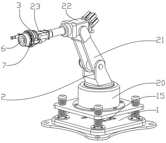
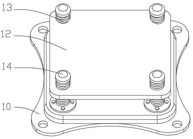
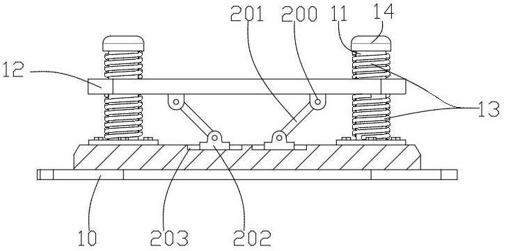
[0027] An auxiliary device for computer vision detection, comprising a first base body 1, the first base body 1 includes a mounting base plate 10, the mounting base plate 10 is provided with a through hole for installation and positioning, and the upper end surface of the mounting base plate 10 is symmetrically provided with a limit post 11. A buffer plate body 12 with holes is arranged above the bottom plate 10 , the buffer plate body 12 is inserted above the limit post 11 , and the buffer p...


PUM


Abstract

The invention discloses a computer vision detection auxiliary device which comprises a first base body, the first base body comprises a mounting bottom plate, a buffer plate body is arranged above the mounting bottom plate, a sliding assembly is arranged between the buffer plate body and the mounting bottom plate, and an adjustable and controllable mechanical arm is arranged on the buffer plate body. A mounting base is arranged at the tail end of the mechanical arm, a damping assembly is arranged on the end face of the mounting base and comprises a third plate body capable of being connected with the camera, extension plates are symmetrically fixed to the side walls of the mounting base, hydraulic rods are inserted into the extension plates in a penetrating mode, and a lamp body capable of illuminating the camera is arranged at the tail end of each hydraulic rod. Vibration of the bottom of the mechanical arm is buffered through the first base body and the sliding assembly when the mechanical arm swings, the mechanical arm can be controlled to adjust the direction of the camera, the damping assembly can absorb vibration energy of the mechanical arm, it is guaranteed that the camera tends to be stable, and the lamp body adjustably illuminates a camera shooting area so that a clearer view can be obtained.

Description

technical field [0001] The invention belongs to the technical field of computers, and in particular relates to an auxiliary device for computer vision detection. Background technique [0002] Computer vision is a simulation of biological vision using computers and related equipment. Its main task is to obtain three-dimensional information of the corresponding scene by processing the collected pictures or videos. Simply put, it is to replace the human eye with a camera and a computer. Machine vision for target recognition, tracking and measurement, and further graphics processing, so that computer processing becomes an image more suitable for human eyes to observe or transmit to instruments for detection. [0003] When performing computer vision inspection, the height and direction of the camera need to be adjusted, and the detection object needs to be illuminated to facilitate better imaging. Therefore, auxiliary devices are required. The functions of the existing auxiliary ...

Claims


Application Information

Patent Timeline
Patent Type & Authority Applications(China)
IPC IPC(8): F16M11/18F16M11/08F16M11/10F16F15/067F16F15/023B08B5/02F16M11/22G03B15/03G03B17/56G03B17/55
CPCF16M11/18F16M11/08F16M11/10F16F15/067F16F15/023B08B5/02F16M11/22G03B15/03G03B17/561G03B17/55
Inventor 李闯禹霄
Owner 深圳玖伍微联信息技术有限公司
Why Eureka
Try Eureka