Plastic steel air duct flange machining device and machining method

A processing device and processing method technology, applied in the field of plastic steel air duct flange processing device, to achieve the effects of high precision, avoiding stress concentration, processing cost and convenience

Active Publication Date: 2022-07-26
TIANJIN AOLIANTE STEEL STRUCTURE INSTALLATION ENG
View PDF3 Cites 0 Cited by
  • Summary
  • Abstract
  • Description
  • Claims
  • Application Information

AI Technical Summary

Problems solved by technology

[0003] The present invention aims to propose a plastic steel air duct flange processing device and processing method to solve the technical problem that no heating is required but the flanging accuracy can still be ensured

Method used


Image

  • Plastic steel air duct flange machining device and machining method
  • Plastic steel air duct flange machining device and machining method
  • Plastic steel air duct flange machining device and machining method

Examples


Embodiment 1

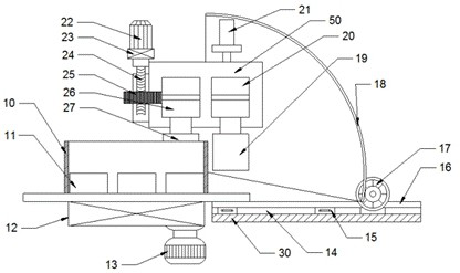
[0041] see attached Figure 1-5 , the fixing component includes a workpiece clamping bracket, a quick chuck 11, a spindle reducer 12 and a first servo motor 13, the annular workpiece 10 is fixed on the workpiece clamping bracket through the quick chuck 11, and the workpiece clamping bracket is passed through the main shaft. The reducer 12 is connected with the first servo motor 13, and the first servo motor 13 controls the rotation and movement of the annular workpiece 10 through the spindle reducer 12 and the quick chuck 11;

[0042] The clamping assembly includes a fixed roller subassembly, a moving roller subassembly, a main fixing table 50 and a lifting cylinder 21;

[0043]The fixed roller sub-assembly includes a fixed bottom roller 19, a fixed shaft block 20, a first ball screw 33, a fourth bracket 34, a fourth planetary reducer 35 and a fourth servo motor 36. The fixed bottom roller 19 is arranged in a fixed position. On the shaft block 20, the fixed shaft block 20 is ...

Embodiment 2

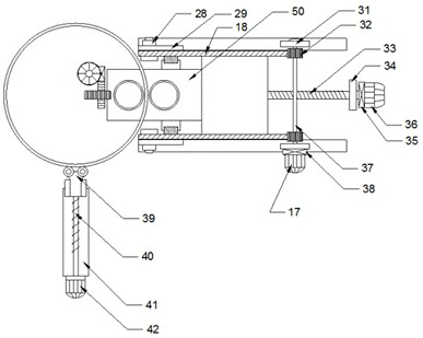
[0065] see Figure 6-8 , Image 6 It is a sectional view of the plastic-steel air duct flange processing device according to the embodiment of the present invention Figure 1 , the state of the preparatory work completed before flanging; Figure 7 It is a sectional view of the plastic-steel air duct flange processing device according to the embodiment of the present invention Figure II , complete the state of flanging; Figure 8 It is a sectional view of the plastic-steel air duct flange processing device according to the embodiment of the present invention Figure 3 , after the flanging is completed, the metal sheet ring returns to its original position.

[0066] Specifically, the plastic-steel air duct flange processing device includes a fixing fixture 70, a flanging portion 80 and a power supply system;

[0067] The fixing fixture 70 is used to fix the end of the air duct to be flanged, and the inner circumference of the fixing fixture 70 includes an arc portion 701 f...


PUM

PropertyMeasurementUnit
Amplitudeaaaaaaaaaa

Abstract

According to the plastic steel air duct flange machining device and method, a first servo motor of a fixing assembly of the device controls an annular workpiece to rotate and move through a main shaft speed reducer and a rapid chuck; a third servo motor of the clamping assembly controls a lead screw worm gear to rotate through a third planetary reducer, controls a pressing lead screw to push or pull a sliding block and controls the clamping distance between a sliding roller and a fixed bottom roller. A second servo motor of the overturning assembly controls a rotating gear to crawl along a gear ring through a second planetary reducer, drives a main fixing table to rotate around a center fixing shaft through a second fixing support and enables a sliding roller and a fixed bottom roller to rotate to drive a clamping part, clamped between the sliding roller and the fixed bottom roller, of the extruded and extended workpiece to overturn, and workpiece flanging is completed. According to the flanging device, heating is not needed in the flanging process, a machined air duct flange is high in precision, the radian formed by flanging is consistent, the end face of the flange is flat, stress concentration of a bent part can be effectively avoided, and the flanging quality is high.

Description

technical field [0001] The invention belongs to the technical field of air duct flange manufacturing, and in particular relates to a plastic-steel air duct flange processing device and a processing method. Background technique [0002] The properties of plastic-steel ducts such as rigidity, elasticity, corrosion resistance, and anti-aging properties are excellent. They are used to form plastic-steel air ducts in ventilation scenarios. They have a long service life and are favored by the market. To meet the needs of the usage scenario, the end of the air duct needs to be processed to form a flange, and the adjacent air ducts are connected and fixed through the flange. At present, the commonly used plastic-steel air duct flanging process is common mechanical flanging equipment. The end of the air duct is flanged through a flanging die, which often needs to be heated and rotated to facilitate the formation of flanging. During flanging processing, usually both the flanging die ...

Claims


Application Information

Patent Timeline
IPC IPC(8): B29C57/00
CPCB29C57/00
Inventor 孙年茂
Owner TIANJIN AOLIANTE STEEL STRUCTURE INSTALLATION ENG
Why Eureka
Try Eureka