Assembly line distribution mechanism and automatic production equipment for packaging boxes

A distribution mechanism and assembly line technology, applied in packaging, transportation and packaging, conveyor objects, etc., can solve problems such as inconsistent production beats

Pending Publication Date: 2022-07-26
南京以太通信技术有限公司
0 Cites 0 Cited by

AI-Extracted Technical Summary

Problems solved by technology

Due to the different job content of the two processes be...

Method used

Gluing equipment 600 duty cycles are shorter than lining bonding mechanism 300 (complete coating time is shorter than bonding time), and the box body 20 that inner wall is coated with bonding agent is shunted to a plurality of by assembly line distribution mechanism 400 The lining bonding mechanism 300 enables the assembly line to maintain maximum efficiency.
[0060] As shown in FIG. 1, the box body 20 is a rectangular carton, and its inner sidewall is pre-coated with an adhesive, such as glue. The inner liner 10 is cardboard, which is bent and placed in the cavity of the box body 20 , and attached to the inner sidewall of t...

Abstract

The invention discloses an assembly line distribution mechanism and automatic production equipment of packaging boxes, the assembly line distribution mechanism comprises a conveyor, a distribution element and a driving assembly, the conveyor is used for conveying objects, the distribution element is arranged above the conveyor, and the distance between the distribution element and the conveyor is smaller than the height of the objects; the driving end of the driving assembly is connected with the distribution element and used for driving the distribution element to move in the conveying direction perpendicular to the conveyor when the objects are conveyed to the positions corresponding to the distribution element, so that the objects are stirred through the distribution element, and the positions, perpendicular to the conveying direction of the conveyor, of the objects are changed. By means of the mode, conveyed objects can be shifted in the direction perpendicular to the conveying direction, and therefore conveying paths of the objects can be distributed.

Application Domain

ConveyorsPaper-making +4

Technology Topic

Assembly lineManufacturing engineering +3

Image

  • Assembly line distribution mechanism and automatic production equipment for packaging boxes
  • Assembly line distribution mechanism and automatic production equipment for packaging boxes
  • Assembly line distribution mechanism and automatic production equipment for packaging boxes

Examples

  • Experimental program(1)

Example Embodiment

[0055] The technical solutions in the embodiments of the present invention will be clearly and completely described below with reference to the accompanying drawings in the embodiments of the present invention. Obviously, the described embodiments are only a part of the embodiments of the present invention, not all of the embodiments. Based on the embodiments of the present invention, all other embodiments obtained by those of ordinary skill in the art without creative efforts shall fall within the protection scope of the present invention.
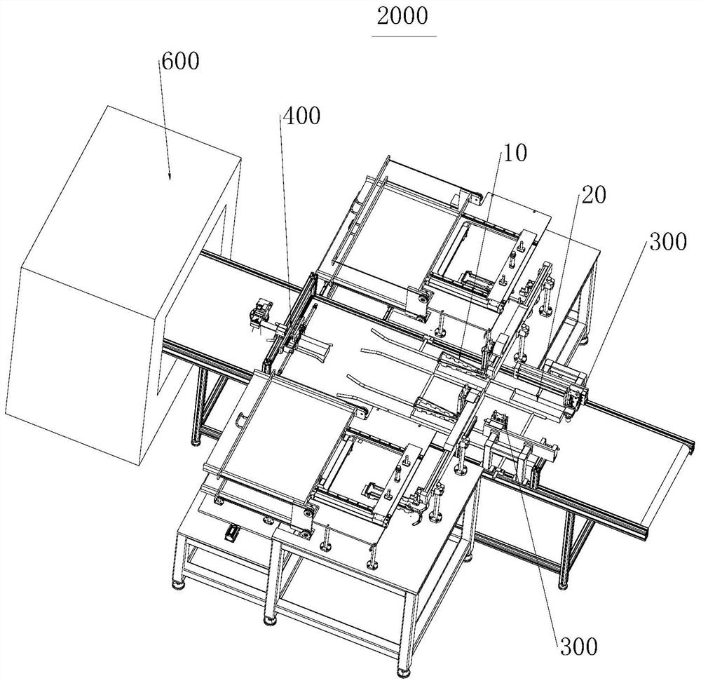
[0056] The present application provides an assembly line distribution mechanism, which includes a conveyor, a distribution element and a drive assembly. The conveyor is used to transfer the objects; the distributing element is arranged above the conveyor, and the distance from the conveyor is less than the height of the object; the driving end of the driving component is connected with the distributing element for when the object is transferred to the corresponding distributing element position At the same time, the distributing element is driven to move in a direction perpendicular to the conveying direction of the conveyor, so as to displace the object through the distributing element, thereby changing the position of the object perpendicular to the conveying direction of the conveyor.
[0057] The present application also provides an automatic production equipment for packaging boxes, including the above-mentioned assembly line distribution mechanism.
[0058] The automatic production equipment of the assembly line distribution mechanism and the packaging box of the present application will be described in detail below with reference to the embodiments. In the following embodiments, the objects conveyed by the conveyor are boxes. In other embodiments, the items conveyed by the conveyor may also be other products.
[0059] see figure 1 , figure 1 It is a schematic diagram of the three-dimensional structure of the box body with the inner lining piece pasted on the inner side wall.
[0060] like figure 1 As shown, the box body 20 is a rectangular paper box, and its inner sidewall is pre-coated with an adhesive, such as glue. The inner lining member 10 is a cardboard, which is bent and placed in the cavity of the box body 20 , and attached to the inner wall of the box body 20 along the circumference of the box body 20 to enhance the strength of the box body 20 .
[0061] The box body 20 can be used as a packaging box, for example, for containing a ceramic dielectric filter.
[0062] see figure 2 , figure 2 The schematic diagram of the structure of different states during the bending and forming process of the inner liner is shown.
[0063] like figure 2 As shown, the liner 10 is initially elongated, with opposing inner and outer sides. Along the length direction, three v-shaped notches 10-1, 10-2, 10-3 are opened at intervals on the inner side to facilitate bending. Three v-shaped cuts 10-1, 10-2, 10-3 divide the lining member 10 into four segments 101, 102, 103, 104. It is the prior art to make a V-shaped cutout to facilitate bending, and will not be repeated here.
[0064] During the bending and forming process, the inner lining member 10 sequentially presents a first bending state, a second bending state and a third bending state.
[0065] Wherein, the first bending state: bending at the v-shaped incisions 10-1 and 10-2, so that the lining member 10 is generally U-shaped; the second bending state: bending at the v-shaped incision 10-3 , so that the end of the inner lining member 10 is generally in the shape of a barb; the third bending state: the two ends of the inner lining member 10 are brought together, so that the inner lining member 10 is generally triangular.
[0066] After the inner lining member 10 in the third bending state is placed in the cavity of the box body 20, due to the removal of the external force, the inner lining member 10 will be elastically deformed to a certain extent to restore its original shape, showing that it expands to the surrounding, and finally roughly The upper part matches the inner side wall of the box body 20 .
[0067] see image 3 , image 3 It is a three-dimensional structural schematic diagram of the automatic production equipment of the packaging box of the present application.
[0068] like image 3 As shown, the present application provides an automated production equipment 2000 for packaging boxes, including a gluing device 600, an assembly line distribution mechanism 400, and a plurality of lining gluing mechanisms 300 (two in this embodiment). In order to apply adhesive to the inner side walls of the box body 20, the assembly line distribution mechanism 400 is used to distribute the plurality of box bodies 20 whose inner side walls are coated with adhesive to a plurality of different conveying paths, and a plurality of lining bonding mechanisms. 300 corresponds to a plurality of different conveying paths one-to-one for adhering the inner lining member 10 to the inner side wall of the box body 20 .
[0069] The working cycle of the gluing equipment 600 is shorter than that of the lining gluing mechanism 300 (the completion time of coating is shorter than the gluing time). Combine mechanism 300 so that the pipeline can maintain maximum efficiency.
[0070] It should be noted that, in this embodiment, the pipeline distribution mechanism 400 distributes the plurality of objects delivered through one transmission path to a plurality of different transmission paths. In other embodiments, the assembly line distribution mechanism 400 can also be used to collect a plurality of objects transferred from a plurality of different transfer paths into one transfer path. Alternatively, multiple objects conveyed from multiple different conveying paths may be assigned to multiple different conveying paths.
[0071] The assembly line distribution mechanism 400 and the lining bonding mechanism 300 will be described in detail below.
[0072] Pipeline distribution mechanism 400:
[0073] see Figure 4 and Figure 5 , Figure 4 is the three-dimensional structural schematic diagram of the pipeline distribution mechanism in the embodiment of the present application, Figure 5 This is the front view of the pipeline distribution mechanism in the embodiment of the present application.
[0074] like Figure 4 and Figure 5 As shown, the line dispensing mechanism 400 includes a conveyor 410 , a dispensing element 420 and a drive assembly 430 . The conveyor 410 is used for conveying the box body 20 ( Figure 5 The distribution element 420 is arranged above the conveyor 410, and the distance from the conveyor 410 is smaller than the height of the box body 20. The driving end of the drive assembly 430 is connected to the distribution element 420 for placing in the box. When the body 20 is conveyed to the position corresponding to the distribution element 420, the distribution element 420 is driven to be perpendicular to the conveying direction of the conveyor 410 ( Figure 5 (up and down direction in the middle) to move the box body 20 through the distributing element 420, so as to change the position of the box body 20 perpendicular to the conveying direction of the conveyor 410.
[0075] In this embodiment, in the conveying direction of the conveyor 410 , a flow guiding element 440 is disposed downstream of the distributing element 420 , and the flow guiding element 440 is fixedly arranged above the conveyor 410 , and has an interval perpendicular to the conveying direction of the conveyor 410 . The provided first conveying passage 441 and the second conveying passage 442 are used to form the conveying path of the box body 20 . A storage area 443 is also formed between the first conveying passage 441 and the second conveying passage 442 for stopping the box body 20 .
[0076] The driving assembly 430 can drive the distributing member 420 to move between three positions perpendicular to the conveying direction of the conveyor 410, and the three positions correspond to the first conveying passage 441, the second conveying passage 442, and the storage area 443, respectively, so as to displace the cassettes. The body 20 is selectively transferred to the first transfer channel 441 , the second transfer channel 442 or the storage area 443 .
[0077] The first conveying channel 441 and the second conveying channel 442 are respectively provided with lining bonding mechanisms 300 . After the box body 20 is transported to the position of the lining bonding mechanism 300 , it is bonded to the lining member 10 . The storage area 443 is used to store unqualified box bodies 20 so as to prevent them from entering subsequent processes.
[0078] In this embodiment, the box body 20 output by the gluing device 600 is transported at the position (center) corresponding to the storage area 443, and the operation process of the driving assembly 430 is as follows:
[0079] The drive assembly 430 drives the distribution element 420 to be located at a position corresponding to the storage area 443;
[0080] When the box body 20 is conveyed to the position of the distributing element 420, the driving assembly 430 drives the distributing element 420 to move to the position corresponding to the first conveying channel 441;
[0081] After the box body 20 leaves the distribution element 420, the drive assembly 430 drives the distribution element 420 to move to the position corresponding to the storage area 443;
[0082] When the next box body 20 is transferred to the position of the distributing element 420, the driving assembly 430 drives the distributing element 420 to move to the position corresponding to the second conveying channel 442;
[0083] After the box body 20 leaves the distribution element 420, the drive assembly 430 drives the distribution element 420 to move to the position corresponding to the storage area 443;
[0084] Repeat the above actions.
[0085] Wherein, if it is detected that the box body 20 is abnormal (detected by the visual inspection component 450 below), the driving component 430 does not act, and the box body 20 is transferred to the storage area 443 .
[0086] The above-mentioned first transmission channel 441 , second transmission channel 442 and storage area 443 are only illustrative and do not limit the present application. The drive assembly 430 may drive the dispensing element 420 to move between more or fewer positions as desired.
[0087] see Image 6 , Image 6 It is a three-dimensional structural schematic diagram of the driving assembly in the embodiment of the present application.
[0088] like Image 6 As shown, the driving assembly 430 includes a fixing frame 431 , a mounting block 432 and a driving unit 433 . The fixed frame 431 is fixed above the conveyor 410, the mounting block 432 is movably connected to the fixed frame 431 in the conveying direction perpendicular to the conveyor 410, and the driving unit 433 is used to drive the mounting block 432 to move, wherein the distribution element 420 is connected to the mounting block 432. Block 432 is fixedly connected.
[0089] The fixing frame 431 can be in the shape of a "door", including a cross beam and two vertical beams, the cross beam is arranged above the conveyor belt of the conveyor 410, and the two vertical beams are respectively fixedly connected to the frame of the conveyor 410 to support the cross beam. The mounting block is connected to the beam. The box body 20 passes under the beam of the fixing frame 431 . The main part of the distributing element 420 is also located under the beam, and the box body 20 is moved under the driving of the driving unit 433 .
[0090] The specific manner in which the mounting block 432 is movably connected to the fixing frame 431 is as follows:
[0091] The drive assembly 430 also includes a sliding rail 434 and a sliding block 435 . The sliding rail 434 is fixed on the fixing frame 431 and extends perpendicular to the conveying direction of the conveyor 410. The sliding block 435 is clamped on the sliding rail 434 and slidingly cooperates with the sliding rail 434, wherein the mounting block 432 is fixed to the sliding block 435 on.
[0092] The mounting block 432 (distributing element 420 ) is guided to move by the sliding rail 434 , so that the moving process is more stable.
[0093] In order to control the movement of the distributing element 420 between the above three positions, the specific structure of the driving unit 433 is as follows:
[0094] The driving unit 433 includes a first driving cylinder 4331 and a second driving cylinder 4332 . The first driving cylinder 4331 includes a first cylinder 4331-1 and a first piston rod 4331-2 that can move relative to the conveying direction of the conveyor 410. The first cylinder 4331-1 is fixed to the fixing frame 431, and the second The driving cylinder 4332 includes a second cylinder 4332-1 and a second piston rod 4332-2 that can move relative to the conveying direction of the conveyor 410. The second cylinder 4332-1 is fixed to the mounting block 432, and the first piston rod 4331-2 and the end of the second piston rod 4332-2 abut and are fixedly connected.
[0095] The first driving cylinder 4331 and the second driving cylinder 4332 may be cylinders.
[0096] The following describes how the drive unit 433 controls the dispensing element 420 in different positions:
[0097] When both the first driving cylinder 4331 and the second driving cylinder 4332 are in the extended state, the distributing element 420 is located at the corresponding first transmission channel 441;
[0098] When the first drive cylinder 4331 is in a retracted state, and when the second drive cylinder 4332 is in an extended state, the distribution element 420 is located at the corresponding storage area 443;
[0099] When both the first driving cylinder 4331 and the second driving cylinder 4332 are in the retracted state, the distributing element 420 is located at the corresponding second transmission channel 442 .
[0100] In order to apply force more evenly when the box body 20 is moved, the distribution element 420 is formed with a guide channel 421, and the guide channel 421 can allow the box body 20 to pass through. When the box body 20 passes through the distributing element 420 , the side edge of the guide channel 421 moves the box body 20 .
[0101] Specifically, the distributing element 420 includes two guide rods 422, each of which extends in the conveying direction of the conveyor 410, and the two guide rods 422 are arranged at intervals perpendicular to the conveying direction of the conveyor 410 to form a guide channel 421. The box body 20 is toggled by the guide rod 422 .
[0102] In order to make the box 20 conveyed on the conveyor 410 enter the guide channel 421 accurately and flow out of the guide channel 421 more smoothly, both ends of each guide rod 422 are respectively bent away from the guide channel 421 to form a chamfered structure.
[0103] In order to sense that the box body 20 is transferred to the dispensing element 420, the assembly line dispensing mechanism 400 further includes a sensor (not shown) and a controller (not shown). The sensor is used to send a first signal when it is detected that the box body 20 is transferred to the position corresponding to the distributing element 420, and the controller is respectively connected to the sensor and the drive assembly 430 for controlling the drive assembly when receiving the first signal. 430 actions.
[0104]In order to detect whether the box body 20 is abnormal, for example, whether the adhesive is missing, the assembly line distribution mechanism 400 further includes a visual detection component 450 (the prior art). The upstream of the dial element 420 is used to send a second signal when it is detected that the box body 20 meets the predetermined condition, and the controller is also connected to the visual detection component 450 for control and control according to the second signal after receiving the second signal. The drive assembly 430 operates.
[0105] Lining bonding mechanism 300:
[0106] see Figure 7 , Figure 7 It is a schematic diagram of the three-dimensional structure of the lining bonding mechanism of the present application.
[0107] like Figure 7 As shown, the liner bonding mechanism 300 includes a handling assembly 340 and a roller drive assembly 360 . The transport assembly 340 is used to place the lining member 10 in the cavity of the box body 20, the roller drive assembly 360 is provided with a roller 370 that can rotate around its own axis, and the roller drive assembly 360 is used to drive the roller 370 to move in three-dimensional space , so that the roller 370 is inserted into the cavity of the box body 20 , presses the inner lining member 10 until the inner lining member 10 is in contact with the inner side wall of the box body 20 , and rolls the inner lining member 10 .
[0108] In the present application, the roller 370 is driven by the roller drive assembly 360 to roll the lining member 10 to bond with the box body 20 , thereby realizing automation and improving work efficiency.
[0109] In order to realize continuous operation, the lining bonding mechanism 300 further includes a first blocking member 330 and a second blocking member 350 . The first blocking member 330 is used to stop the box body 20. In the conveying direction of the conveyor 410, the second blocking member 350 is disposed downstream of the first blocking member 330, and is used to stop the box body 20 on which the lining member 10 is placed. .
[0110] In this embodiment, the structures of the first blocking member 330 and the second blocking member 350 are the same. The following takes the second blocking member 350 as an example to introduce its specific structure:
[0111] The second blocking member 350 includes an air cylinder 352 and a blocking member 351 . The blocking element 351 is an angle iron and has two mutually perpendicular side walls, one of which is fixed to the driving end of the cylinder 352 , and the other side wall is used to block the box body 20 . The blocking element 351 is driven by the air cylinder 352 to move in position, thereby blocking the box body 20 .
[0112] The first blocking member 330 and the second blocking member 350 are not limited to the above structures, and other structures, such as commercially available blocking cylinders, may also be used in other embodiments.
[0113] Action process:
[0114] When the box body 20 is conveyed to the position corresponding to the first blocking member 330 driven by the conveyor 410, the first blocking member 330 acts to stop the box body 20; the transport component 340 transports the inner lining member 10 in the third bending state to In the cavity of the box body 20; the first blocking member 330 acts to release the box body 20 with the lining member 10 placed there; At the position of 350, the second blocking member 350 acts to stop the box body 20 on which the lining member 10 is placed; the roller drive assembly 360 acts to drive the roller 370 to roll the lining member 10 to bond with the box body 20; The second blocking member 350 acts to release the box body 20 .
[0115] In the above manner, a plurality of boxes 20 can be conveyed through the conveyor 410 in sequence, so as to realize the continuous bonding operation and improve the work efficiency.
[0116] The first conveying passage 441 and the second conveying passage 442 on the guide element 440 can limit the conveying path of the box body 20 on the conveyor 410, so that the conveying assembly 340 can accurately place the liner 10, and the roller 370 can accurately roll Press the liner 10.
[0117] To sum up, those skilled in the art can easily understand that the automatic production equipment of the assembly line distribution mechanism and the packaging box provided by this application at least has the following advantages:
[0118] The distributing element is driven by the drive assembly to move perpendicular to the conveying direction, so as to move the conveyed object, and the conveying path of the object can be distributed.
[0119] The above are only the embodiments of the present application, and are not intended to limit the scope of the patent of the present application. Any equivalent structure or equivalent process transformation made by using the contents of the description and drawings of the present application, or directly or indirectly applied in other related technical fields, All are similarly included in the scope of patent protection of the present invention.

PUM

no PUM

Description & Claims & Application Information

We can also present the details of the Description, Claims and Application information to help users get a comprehensive understanding of the technical details of the patent, such as background art, summary of invention, brief description of drawings, description of embodiments, and other original content. On the other hand, users can also determine the specific scope of protection of the technology through the list of claims; as well as understand the changes in the life cycle of the technology with the presentation of the patent timeline. Login to view more.
Why Eureka
Try Eureka