
Exhaust device of washing and drying machine and washing and drying machine

A technology for exhaust devices and washing and drying machines, which is applied to washing devices, other washing machines, washing machines with containers, etc., which can solve problems such as pollution, large energy consumption, and air quality that cannot be guaranteed for a long time, and achieve high blocking effect and high efficiency. The effect of the reflow effect

Pending Publication Date: 2022-07-26
YUNMI HULIAN TECH (GUANGDONG) CO LTD
View PDF0 Cites 0 Cited by
  • Summary
  • Abstract
  • Description
  • Claims
  • Application Information

AI Technical Summary

Problems solved by technology

The direct drying method consumes a lot of energy; the dried gas is mostly high-temperature and high-humidity gas, and the high-temperature and high-humidity gas after drying is directly discharged from the inner cylinder to the room, which will cause indoor air humidity and humidity. The temperature is too high, and the indoor air with high temperature and humidity enters the inner cylinder through the fresh air duct, resulting in the air quality not being guaranteed for a long time, and easily causing damage and pollution of clothes drying
[0003] In other existing technologies, the condensed air with high temperature and humidity is cooled and dehumidified by the heat exchange device and then discharged outside the clothes drying device. However, even if the condensed gas is discharged after being cooled and dehumidified by the heat exchange device, it still cannot be completely removed. liquid in gas

Method used


Image

  • Exhaust device of washing and drying machine and washing and drying machine
  • Exhaust device of washing and drying machine and washing and drying machine
  • Exhaust device of washing and drying machine and washing and drying machine

Examples


Embodiment Construction

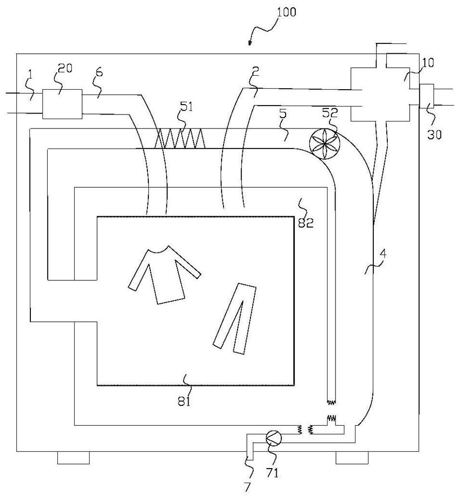
[0035] The present invention will be further described in detail below in conjunction with the accompanying drawings, and the foregoing and other objects, features, aspects and advantages of the present invention will become more apparent, so that those skilled in the art can implement them with reference to the description. In the drawings, the shapes and dimensions may be exaggerated for clarity, and the same reference numerals will be used throughout the drawings to refer to the same or like parts. In the following description, terms such as center, thickness, height, length, front, back, rear, left, right, top, bottom, upper, lower, etc. are based on the orientation or positional relationship shown in the drawings. In particular, "height" corresponds to the size from top to bottom, "width" corresponds to the size from left to right, and "depth" corresponds to the size from front to back. These relative terms are for convenience of description and are generally not intended...


PUM


Abstract

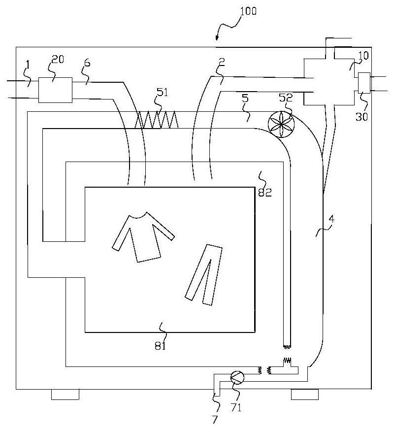
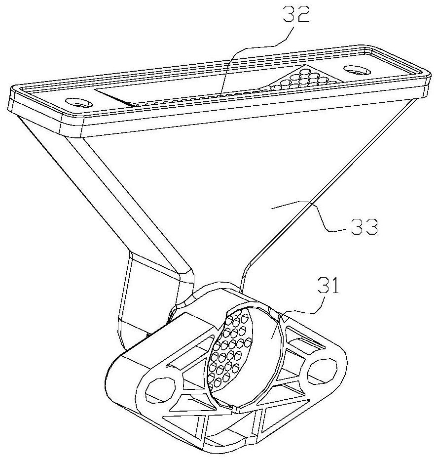
The invention relates to an exhaust device of a washing and drying machine. The exhaust device is installed on the inner wall or the outer wall of a shell of the washing and drying machine. Comprising an air inlet, an exhaust channel and an exhaust port. The air inlet, the exhaust channel and the exhaust port form an exhaust passage; a blocking structure for blocking liquid is arranged in the exhaust passage; the air inlet guides air which is exhausted by the washing and drying machine and has a humidity difference with the outside into the exhaust channel, liquid in the air flows back after passing through the blocking structure, and the air is exhausted out of the washing and drying machine from the exhaust port. The size of the washing and drying machine is not increased, gas which is exhausted by the washing and drying machine and has a humidity difference with the outside is guided into the exhaust channel, liquid in the gas flows back after passing through the blocking structure, and a small amount of liquid in the gas is prevented from flowing to the ground after being sprayed out along with the gas; and due to the inclined plane design of the first baffle plate in the blocking structure and the combined design of the first baffle plate and the second baffle plate, higher liquid blocking effect and backflow effect can be realized.

Description

technical field [0001] The invention relates to the technical field of clothing care, in particular to an exhaust device of a washing and drying machine and a washing and drying machine. Background technique [0002] At present, the existing clothes drying devices, such as dryers and integrated washing and drying machines, use condensing circulating drying. Under the action, the water on the clothes evaporates and the air forms moist and hot air, and then the moist and hot air enters the condenser. Then enter the cylinder, and after such a cycle, the purpose of drying clothes is achieved. The second is straight-through condensation, which introduces fresh air from the outside, and directly discharges it from the dryer after drying. The direct exhaust drying method consumes a lot of energy; the gas after drying is mostly high-temperature and high-humidity gas, and the high-temperature and high-humidity gas after drying is directly discharged from the inner cylinder into the...

Claims


Application Information

Patent Timeline
IPC IPC(8): D06F39/00D06F25/00
CPCD06F39/00D06F25/00
Inventor 陈小平李宁宁李维玉张宝鸽
Owner YUNMI HULIAN TECH (GUANGDONG) CO LTD
Learn More