
Intelligent gangue blocking net protection method, system and device

A technology of protection system and gangue-blocking net, which is applied in mining devices, measuring devices, earthwork drilling and mining, etc., can solve the problems of increasing mine cost, short service life, and high replacement frequency, and achieve the effect of reducing replacement frequency and increasing blocking effect

Pending Publication Date: 2021-11-30
XIAN UNIV OF SCI & TECH
View PDF0 Cites 0 Cited by
  • Summary
  • Abstract
  • Description
  • Claims
  • Application Information

AI Technical Summary

Problems solved by technology

However, since most researchers currently solve and deduce the equipment parameters of the retaining net based on high-speed cameras or stress sensors and other measurement methods, and most of them use analogy and empirical design methods, the proportion of human subjective factors is difficult to fully consider in theoretical calculations. The influence of the dynamic characteristics of the damage on the gangue-retaining net, which leads to unreasonable equipment parameters of the gangue-retaining net
Therefore, the current gangue retaining net usually has a short service life and high replacement frequency in the working face, and the blocking effect is not good, which further increases the cost of the mine.

Method used


Image

  • Intelligent gangue blocking net protection method, system and device
  • Intelligent gangue blocking net protection method, system and device
  • Intelligent gangue blocking net protection method, system and device

Examples


Embodiment Construction

[0069] DETAILED DESCRIPTION OF THE PREFERRED EMBODIMENTS It should be understood that the specific embodiments described herein are intended to illustrate and explain the disclosure and is not intended to limit the disclosure.

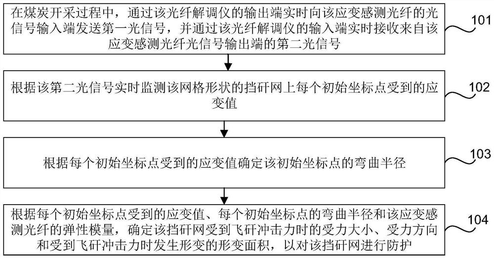
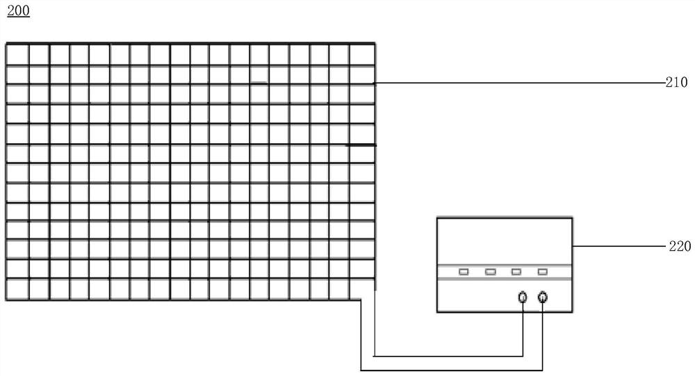
[0070] figure 1 It is a flow chart of a smart shaving network protection method according to an exemplary embodiment, such as figure 1 As shown, this method is applied to figure 2 The smart ignition network protection system, which includes: a strain sensing fiber and fiber optic demodulator, the strain sensing fiber is arranged into a mesh-shaped shaped shaft 210 and is placed in the Feiyi Used to block the pan, the light signal input of the strain sensing fiber is connected to the output of the optical fiber demodulator 220, which is connected to the input of the fiber demodulator 220. It should be noted that in the intelligent shaping network protection system, the strain sensing fiber generally uses a metal base strain sensing fiber having a diameter ...


PUM


Abstract

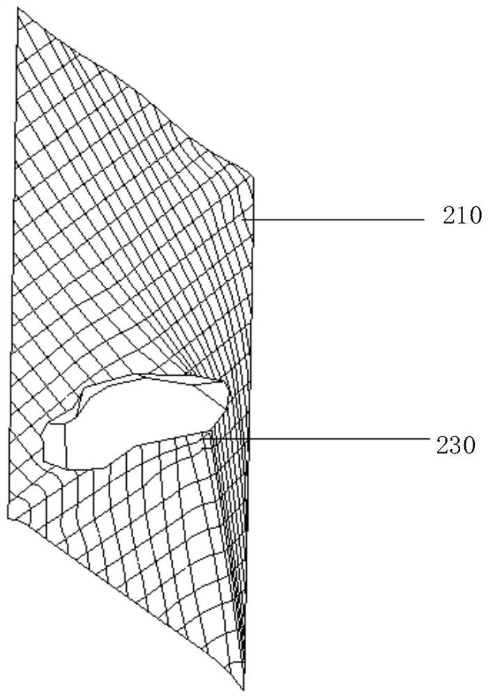
The invention relates to an intelligent gangue blocking net protection method, system and device. The method comprises the steps: receiving a second optical signal from the optical signal output end of a strain sensing optical fiber in real time through the input end of an optical fiber demodulator in a coal mining process; monitoring the strain value of each initial coordinate point on a grid-shaped gangue blocking net in real time according to the second optical signal; determining the bending radius of each initial coordinate point according to the strain value of the initial coordinate point; and according to the strain value borne by each initial coordinate point, the bending radius of each initial coordinate point and the elastic modulus of the strain sensing optical fiber, determining the stress size, the stress direction and the deformation area of the gangue blocking net when the gangue blocking net is subjected to flying gangue impact force, so that the gangue blocking net is protected. The size and the direction of the impact force of flying gangue on the gangue blocking net and the deformation of the gangue blocking net during impact of the flying gangue can be directly monitored through the strain sensing optical fiber, so that the local position of the gangue blocking net is reinforced, and the gangue blocking effect is improved.

Description

Technical field [0001] The present disclosure relates to derivatives seam disaster protection technologies, and in particular, relates to an intelligent network protection stopper Gangue method, system and apparatus. Background technique [0002] Seam with increasing angle during mining, large elevation lower end surface of the work, and a face sheet to help, resulting in the risk of roof leaking from the mother fly Refuse accelerated migration to a lower portion of the longwall face under gravity, impact harm people or damage to the equipment when huge. Currently, protective equipment for protecting the fly waste rock gangue impact damage include: blocking network gangue, gangue stopper plate, and an anti-blocking refuse door bracket having a hydraulic partings perspective protection and the like. Wherein the stopper refuse network is a cord twisted from a certain diameter, it is blocked from coal fly waste in the work area flexible braid migrated into the operation area of ​​th...

Claims


Application Information

Patent Timeline
IPC IPC(8): E21F17/18E21F17/00E21C35/04G01D21/02
CPCE21F17/18E21F17/00E21C35/04G01D21/02
Inventor 柴敬欧阳一博张丁丁
Owner XIAN UNIV OF SCI & TECH
Learn More