Shell body, main reducer provided with same and vehicle

A shell and shell technology, applied in the field of vehicles, can solve problems such as bad feedback, weakened oil retaining effect, oil leakage, etc., to reduce the possibility, improve the blocking effect, and solve the effects of oil leakage and oil leakage

Pending Publication Date: 2020-09-04
BAIC GRP ORV CO LTD
View PDF0 Cites 0 Cited by
  • Summary
  • Abstract
  • Description
  • Claims
  • Application Information

AI Technical Summary

Problems solved by technology

However, because the gear of the main reducer has a stirring effect on the gear oil during operation, especially the oil rejection during high-speed operation, the oil retaining effect of the pressure relief structure at this place is weakened. After the oil passes through the pressure relief passage 12, it will Driven by the air flow, the accumulation at the check valve 30 will overflow together with the high-pressure gas when the check valve 30 is opened to release pressure, and then the oil leakage problem will appear, causing complaints from customers and bad market the feedback

Method used


Image

  • Shell body, main reducer provided with same and vehicle
  • Shell body, main reducer provided with same and vehicle
  • Shell body, main reducer provided with same and vehicle

Examples


Embodiment Construction

[0026] In order to make the purpose, technical solutions and advantages of the embodiments of the present invention more clear, the following will clearly and completely describe the technical solutions of the embodiments of the present invention in conjunction with the drawings of the embodiments of the present invention. Apparently, the described embodiments are some, not all, embodiments of the present invention. All other embodiments obtained by those skilled in the art based on the described embodiments of the present invention belong to the protection scope of the present invention.

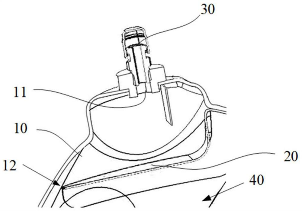
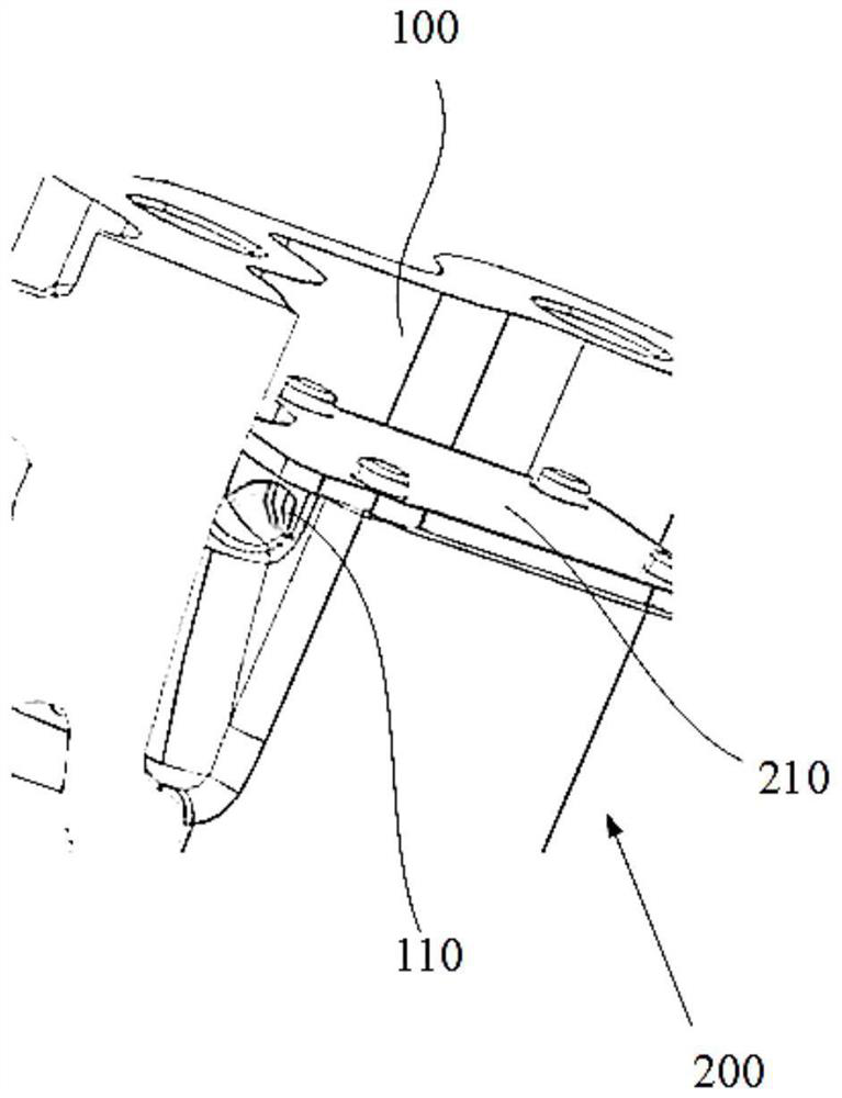
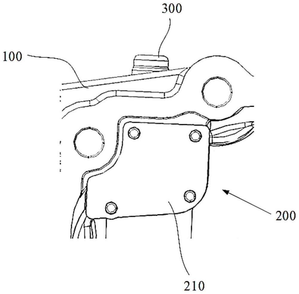
[0027] The casing according to the embodiment of the present invention will be described in detail below in conjunction with the accompanying drawings. The casing includes: a casing 100 and a blocking structure 200. The casing 100 is provided with a main cavity 120, a pressure relief channel 110 and a pressure relief hole 130. The pressure relief channel 110 and the pressure relief hole 130...


PUM


Abstract

The invention provides a shell body, a main reducer provided with the same and a vehicle. The shell body comprises an outer shell and a blocking structure; a main cavity, a decompression passage and adecompression hole are formed in the outer shell; the decompression passage and the decompression hole communicate with the main cavity respectively and the decompression passage communicates with the decompression hole; the blocking structure comprises an enclosure bulkhead and at least one oil blocking plate; the enclosure bulkhead is attached to the inside of the outer shell; the enclosure bulkhead and the outer shell jointly limit to form a blocking cavity; the blocking cavity is positioned between an outlet of the decompression passage and the decompression hole; and the oil blocking plate is positioned in the blocking cavity and is attached to the outer shell, so the blocking cavity is divided into at least two blocking subcavities which communicate with each other. The blocking mechanism improves the effect of blocking oil liquid and prevents the oil liquid from passing through and reaching the position of a one-way valve positioned in the decompression hole, so the problems ofoil impregnation and oil leakage at the position of the one-way valve are finally solved.

Description

technical field [0001] The invention relates to the field of vehicles, in particular to a housing, a final reducer with the same and a vehicle. Background technique [0002] In the main reducer assembly of the front axle of an off-road vehicle, a check valve 30 of the Q900B type is used for pressure relief. Isolation, leaving a smaller pressure relief channel 12 for exhaust, the specific structure is as follows figure 1 shown. However, because the gear of the main reducer has a stirring effect on the gear oil during operation, especially the oil rejection during high-speed operation, the oil retaining effect of the pressure relief structure at this place is weakened. After the oil passes through the pressure relief passage 12, it will Driven by the air flow, the accumulation at the check valve 30 will overflow together with the high-pressure gas when the check valve 30 is opened to release pressure, and then the oil leakage problem will appear, causing complaints from cust...

Claims


Application Information

Patent Timeline
IPC IPC(8): F16H57/029F16H57/027
CPCF16H57/027F16H57/029F16H2057/02052
Inventor 胡颂韩吴祥超肖军周渝
Owner BAIC GRP ORV CO LTD
Why Eureka
Try Eureka