Weak current control cabinet of smart home system
A smart home system, electrical control technology, applied in the direction of electrical components, chassis/cabinet/drawer parts, separation methods, etc., can solve the problems of damping components, affecting cleaning, disharmony, etc., to avoid drying devices , to avoid artificial replacement, the effect of easy to use
- Summary
- Abstract
- Description
- Claims
- Application Information
AI Technical Summary
Problems solved by technology
Method used
Image
Examples
Embodiment 1
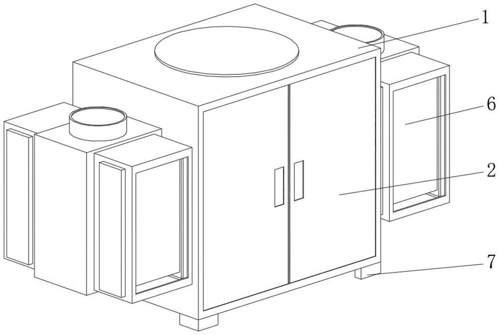
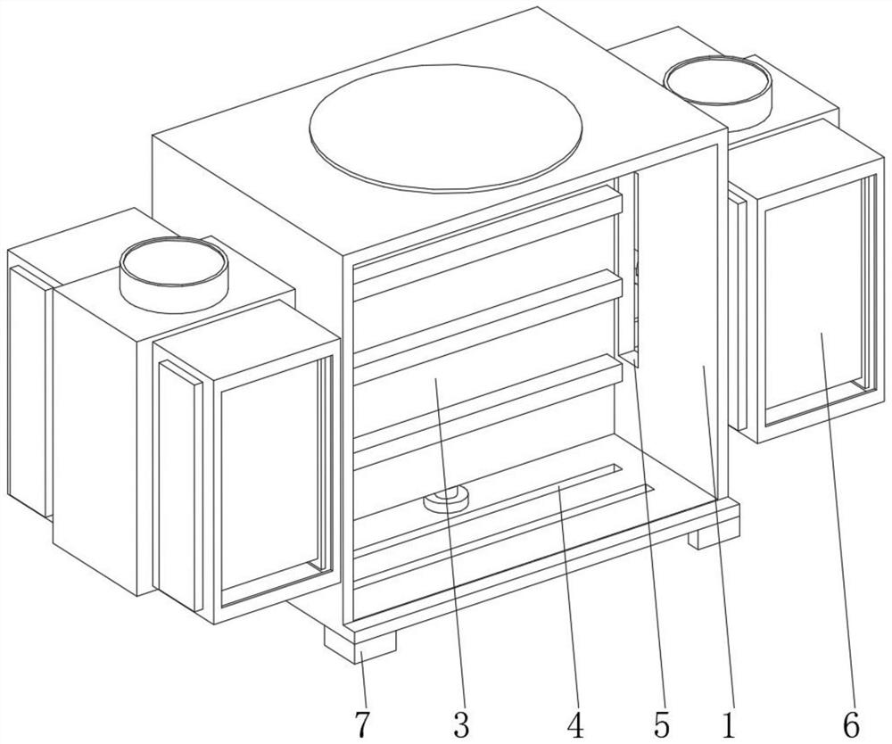
[0029] see Figure 1-Figure 3, the present invention provides a technical solution: a weak current control cabinet for a smart home system, comprising a cabinet body 1, a cabinet door 2 is opened on one side of the cabinet body 1, a mounting frame 3 is fixedly connected to the inner wall of the cabinet body 1, and a bottom of the cabinet body 1 is opened. There is a ventilation hole 4, a dustproof net is arranged inside the ventilation hole 4, a communication hole 5 is opened on both sides of the cabinet body 1, and a dehumidification device 6 is connected to both sides of the cabinet body 1 through the communication hole 5, and the four corners of the bottom of the cabinet body 1 are all connected. Fixed connection with outriggers 7;
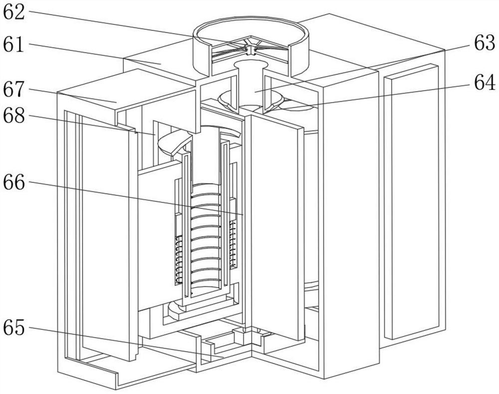
[0030] The dehumidification device 6 includes a dehumidification box 61 , a fan 62 is fixedly connected to the top of the dehumidification box 61 , the air inlet of the fan 62 is provided with a filter screen, and the top of the inner wall of t...
Embodiment 2
[0035] see Figure 1-Figure 4 , On the basis of the first embodiment, the present invention provides a technical solution: the drying device 66 includes a support frame 661, a partition plate 662 is fixedly connected to the top of the support frame 661, and a drying cylinder 663 is fixedly connected on both sides of the partition plate 662. A sealing plate 664 is fixedly connected to the side of the 663 away from the partition plate 662, and a sealing plug 665 is fixedly connected to both sides of the partition plate 662 and the side of the sealing plate 664 close to the drying cylinder 663. The slider is fixedly connected, the top ends of the support frame 661 are fixedly connected to the bottom of the drying cylinder 663, the shape and size of the sealing plug 665 are all matched with the drying sliding hole 68, and the sealing plate 664 is arranged inside the drying box 67, with a The drying device 66 is provided with two sets of drying cylinders 663 inside the drying devic...
Embodiment 3
[0037] see Figure 1-Figure 5 , on the basis of Embodiment 1 and Embodiment 2, the present invention provides a technical solution: the drying cylinder 663 includes a double-layer mesh cylinder 6631, the double-layer mesh cylinder 6631 is filled with a desiccant, and both sides of the double-layer mesh cylinder 6631 slide. A connecting plate 6632 is connected, and the side of the connecting plate 6632 close to the double-layer mesh cylinder 6631 is provided with a limit chute 6633, the inner wall of the limit chute 6633 is slidably connected with a support slider 6634, and the bottom of the support slider 6634 is fixedly connected with a support spring 6635 , the bottom of the support spring 6635 is fixedly connected with the bottom of the inner wall of the limit chute 6633, the bottom of the double-layer mesh cylinder 6631 is fixedly connected with a pressure switch 6636, the top of the inner wall of the double-layer mesh cylinder 6631 is slidably connected with a lower ball h...
PUM
 Abstract
Description
Claims
Application Information
 - R&D
- Intellectual Property
- Life Sciences
- Materials
- Tech Scout
- Unparalleled Data Quality
- Higher Quality Content
- 60% Fewer Hallucinations
Browse by: Latest US Patents, China's latest patents, Technical Efficacy Thesaurus, Application Domain, Technology Topic, Popular Technical Reports.
© 2025 PatSnap. All rights reserved.Legal|Privacy policy|Modern Slavery Act Transparency Statement|Sitemap|About US| Contact US: help@patsnap.com


