Bicycle wireless charging device

A wireless charging and bicycle technology, applied in circuit devices, battery circuit devices, collectors, etc., can solve the problems of incomplete protection and low charging efficiency

Pending Publication Date: 2022-07-26
QINGDAO MAGENE INTELLIGENCE TECH CO LTD
View PDF0 Cites 0 Cited by
  • Summary
  • Abstract
  • Description
  • Claims
  • Application Information

AI Technical Summary

Problems solved by technology

[0003] The technical problem to be solved by the present invention is: to overcome the defects of low charging efficiency and incomplete protection of the existing bicycle wireless charging structure, and provide a bicycle wireless charging device, which combines the unique structure of bicycles and arranges the receiving end in the hollow shaft connecting tube The coil, combined with the structural design of the cylindrical transmitting end device, provides more space than the built-in coil of the sensor to increase the number of winding turns of the induction coil and the coupling degree of the coil, thereby improving the charging efficiency. At the same time, the entire charging mechanism is set on the central axis and The inside of the central axis connecting pipe, and the extension line is sealed with glue, so as to realize the comprehensive protection of the charging mechanism

Method used


Image

  • Bicycle wireless charging device
  • Bicycle wireless charging device
  • Bicycle wireless charging device

Examples


Embodiment approach 1

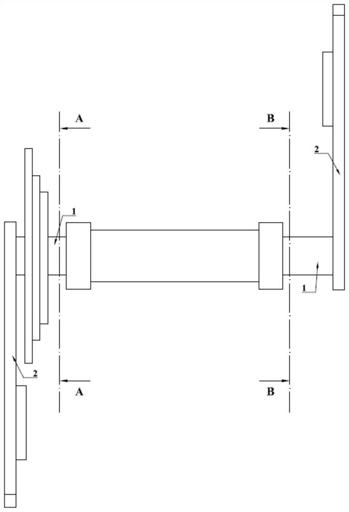
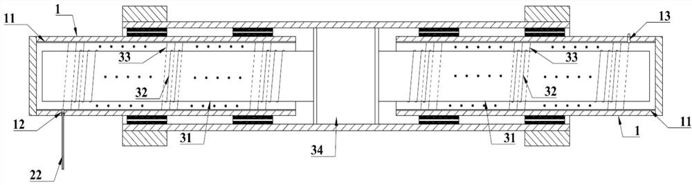
[0025] Embodiment 1: as figure 1 , 2 As shown in the figure, the bicycle wireless charging device includes a pair of hollow central shaft communication pipes 1 rotatably connected to both ends of the central shaft of the bicycle, a crank 2 mounted on the outer end of the central shaft communication pipe 1, fixed in the bicycle central shaft and inserted in the The charging mechanism 3 in the communication pipe 1, the input end of the charging mechanism 3 is connected to the power supply module, and the output end of the charging mechanism 3 extends through the central axis communication pipe 1 to the power meter inside the crank 2, wherein the The charging mechanism 3 includes a non-metallic cylinder 31 that is fixedly connected to the central shaft of the bicycle and inserted into the central shaft communicating tube 1 , a transmitter coil 32 wound on the non-metallic cylinder 31 , and a side wall of the central shaft communicating tube 1 . The receiving end coil 33 coupled ...

Embodiment approach 2

[0026] Embodiment 2: A magnetic conductive material layer 11 is attached to the inner wall of the central axis communication tube 1 of the bicycle wireless charging device, and the transmitting coil 32 is wound on the inner surface of the magnetic conductive material layer 11 . Further, the magnetic conductive material layer 11 is a ferrite cylinder. The magnetic circuit between the high transmitter coil and the receiver coil is strengthened to further improve the coupling efficiency. The non-inserted part of the non-metallic cylinder 31 is glued and fixed on the inner wall of the center axle of the bicycle, and the inserted part of the non-metallic cylinder 31 is tightly fitted with the center axle communication pipe 1 . The remaining structures and components are as described in Embodiment 1 and will not be described again.

Embodiment approach 3

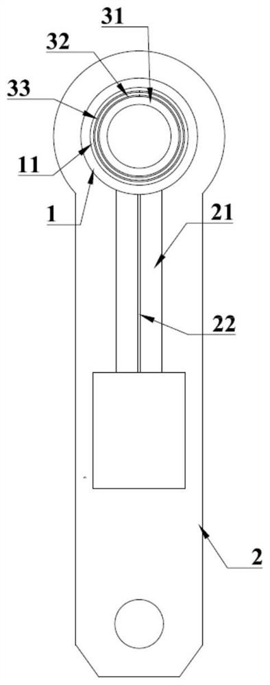
[0027] Embodiment 3: as image 3 , 4As shown in the figure, the crankshaft 2 on the side close to the crankset of the bicycle wireless charging device is provided with a wire groove 21, the central axle communication tube 1 on the side close to the crankset is provided with a wire hole 12, and the receiving end on the side close to the crankset is provided with a wire hole 12. The coil 33 extends through the rectifier module 35 through the extension wire 22 through the wire hole 12 and extends along the wire slot 21 to the installation position of the power meter. Since the end of the crank is fixedly connected with the central shaft communication pipe, the charging line of the crank can be directly extended to the equipment on the crankshaft. The crankshaft 2 on the side away from the crankset is provided with a wire slot 21, and a conductor post 23 is arranged inside the wire slot 21, and an elastic contact post 13 is provided on the end of the central axle communication tu...


PUM


Abstract

The invention relates to a bicycle wireless charging device which comprises a center shaft communicating pipe, a crank and a charging mechanism, and the charging mechanism comprises a non-metal cylinder which is fixedly connected to a bicycle center shaft and inserted into the center shaft communicating pipe. The charging device comprises a non-metal cylinder, a center shaft communicating pipe, a transmitting end coil wound on the non-metal cylinder, a receiving end coil wound on the side wall of the center shaft communicating pipe and coupled with the transmitting end coil, a charging module fixed on the non-metal cylinder and connected with the transmitting end coil, and a rectification module fixed in the center shaft communicating pipe and connected with the receiving end coil. According to the bicycle wireless charging device, the receiving end coil is arranged in the hollow middle shaft communicating pipe, the structural design that the cylindrical sending end equipment is inserted in a matched mode is adopted, more space is provided, the number of winding turns of the induction coil and the coil coupling degree are improved, the charging efficiency is improved, meanwhile, the whole charging mechanism is arranged in the middle shaft and the middle shaft communicating pipe, and the charging efficiency is improved. And the extension circuit is sealed by glue, so that comprehensive protection of the charging mechanism is realized.

Description

technical field [0001] The invention relates to the technical field of bicycle accessories and wireless charging, in particular to a bicycle wireless charging device. Background technique [0002] At present, more and more intelligent devices are being applied to bicycles, including power meters on bicycles used by professional athletes. The existing power supply methods of the bicycle power meter mainly include non-rechargeable button battery power supply and rechargeable lithium battery power supply, and these two kinds of batteries have problems that cannot be ignored in updating electric energy. Among them, the button battery needs to be replaced, which increases the operation However, the existing wireless charging method is realized by the principle of electromagnetic induction. This method requires the distance between the sending and receiving device coils to be as small as possible to ensure the charging efficiency. Therefore, the distance between the charging board...

Claims


Application Information

Patent Timeline
Patent Type & Authority Applications(China)
IPC IPC(8): H02J7/00H02J50/12H02J50/70
CPCH02J7/0042H02J50/12H02J50/70
Inventor 吴曰超孙学斌
Owner QINGDAO MAGENE INTELLIGENCE TECH CO LTD
Why Eureka
Try Eureka