
Pharmaceutical oscillating granulator with material guiding function

A swinging granulator and granulator technology are applied in the direction of granulation of vibration devices, making medicines into special physical or ingestible devices, etc., which can solve the problems of console failure, material collection influence, lack of barrel fixation, etc., and achieve Improve processing efficiency, avoid blockage, and save manpower

Pending Publication Date: 2022-07-29
何亚伟
View PDF7 Cites 0 Cited by
  • Summary
  • Abstract
  • Description
  • Claims
  • Application Information

AI Technical Summary

Problems solved by technology

[0004] 1. When the existing swinging granulator is in use, due to the limited space inside the granulator, the operator needs to add raw materials to the inside of the granulator all the time, which is not only time-consuming and laborious, but also greatly reduces the efficiency of drug production;
[0005] 2. When the existing swing pellet machine is in use, it is necessary to place a barrel containing the material at the bottom of the pellet machine, but the existing device lacks the fixing of the barrel, so that the material barrel is prone to displacement during work. Thus affecting the collection of processed materials;
[0006] 3. When the existing swing pellet machine is in use, long-term use will cause a large amount of heat to be generated inside the console. If the heat cannot be dissipated in time, it will cause internal failure of the console. Thus affecting the use of the swing pellet machine

Method used


Image

  • Pharmaceutical oscillating granulator with material guiding function
  • Pharmaceutical oscillating granulator with material guiding function
  • Pharmaceutical oscillating granulator with material guiding function

Examples


Embodiment 1

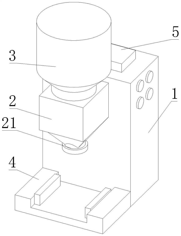
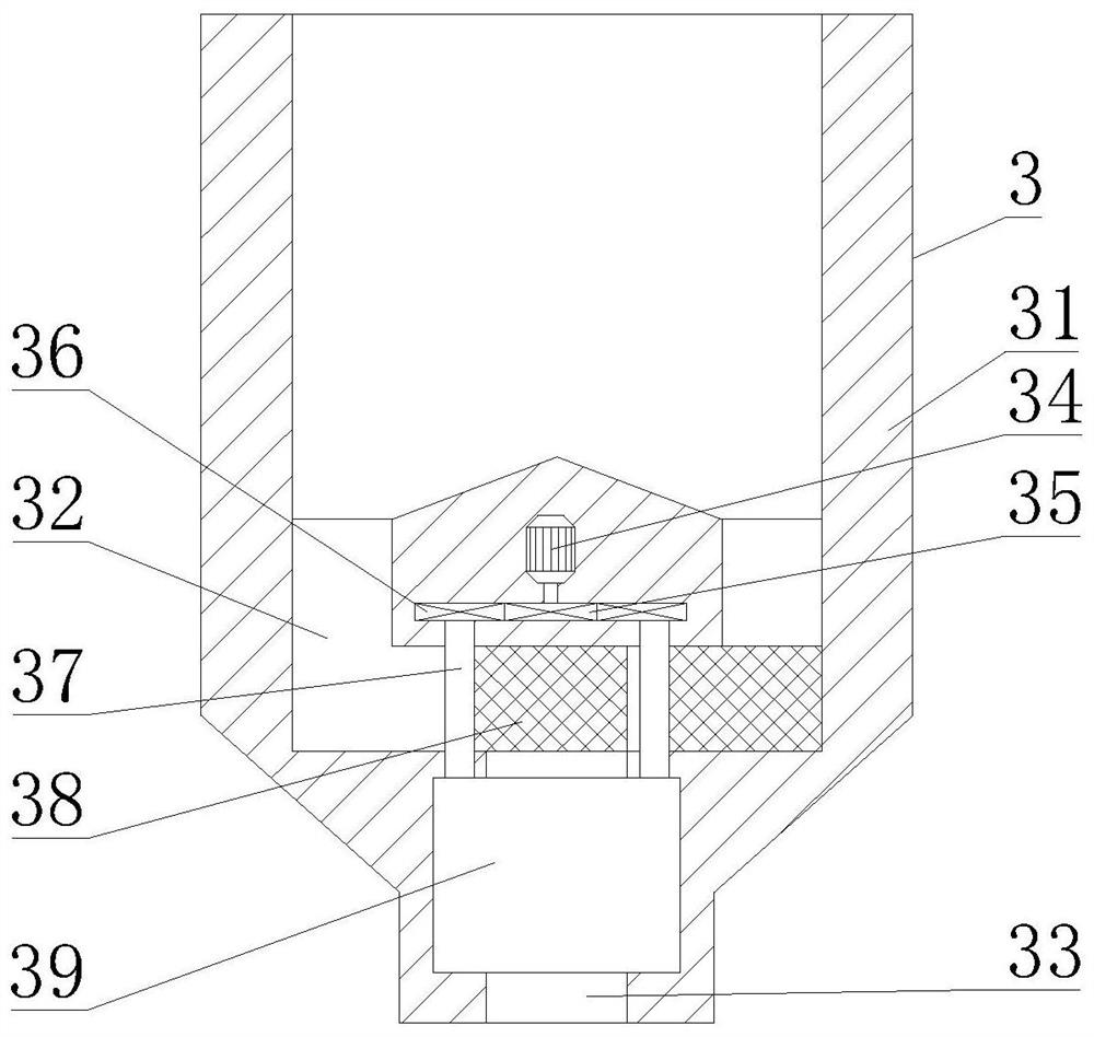
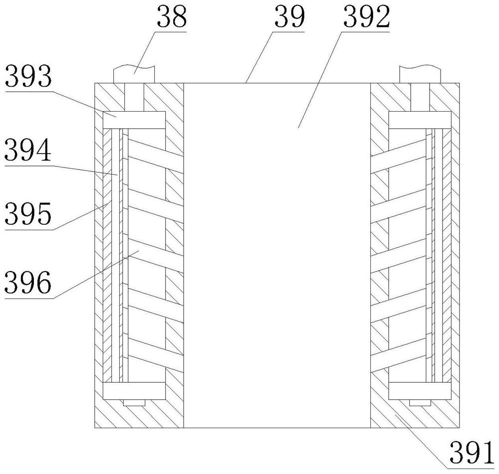
[0039] like Figure 1-6As shown, the present invention provides a pharmaceutical swinging granulator with a feeding function, comprising a console 1, a granulator body 2 is fixedly connected to the top of the front end of the console 1, and a discharge pipe is fixedly connected to the bottom end of the granulator body 2 21. The top of the pellet machine main body 2 is fixedly connected with a feeding bucket 3, the bottom end of the console 1 is fixedly connected with a fixed base 4, and the top of the console 1 is fixedly connected with a heat dissipation mechanism 5. The feeding bucket 3 includes a hopper 31, and the hopper 31 is fixed Connected to the top of the pellet machine main body 2, the middle of the hopper 31 is provided with a feeding groove 32, the bottom end of the hopper 31 is provided with a discharge groove 33, the middle of the hopper 31 is fixedly connected with a first motor 34, the output shaft of the first motor 34 A driving wheel 35 is fixedly connected, ...

Embodiment 2

[0042] like Figure 1-6 As shown, on the basis of Embodiment 1, the present invention provides a technical solution: preferably, the fixed base 4 includes a connection base 41, the connection base 41 is fixedly connected to the bottom end of the console 1, and the middle of the connection base 41 is provided with The slot 42 is placed, the second motor 43 is fixedly connected to the inner two sides of the connecting seat 41, the output shaft of the second motor 43 is fixedly connected with a threaded rod 44, and the side of the threaded rod 44 is threadedly connected with a threaded slider 45. The threaded slider The side of 45 is movably connected with the ejector rod 46, and one end of the ejector rod 46 is movably connected with a fixed plate 47, which is movably connected to the side of the placement slot 42, and the fixed plate 47 includes a plate body 471, and the plate body 471 is movably connected to the ejector rod. At one end of 46, a top block 472 is movably connect...

Embodiment 3

[0045] like Figure 1-6 As shown, on the basis of Embodiment 1, the present invention provides a technical solution: preferably, the heat dissipation mechanism 5 includes a heat dissipation box 51, the heat dissipation box 51 is fixedly connected to the top of the console 1, and the inner two sides of the heat dissipation box 51 are opened There is an exhaust hole 52, an air intake hole 53 is opened in the inner center of the heat dissipation box 51, a fan 54 is fixedly connected to the bottom end of the inner wall of the exhaust hole 52, and a dustproof net 55 is fixedly connected to the top of the heat dissipation box 51. A heat-absorbing plate 56 is fixedly connected inside, a heat-dissipating fin 57 is fixedly connected to the side of the heat-absorbing plate 56 , and a semiconductor refrigeration fin 58 is fixedly connected to the inside of the heat-dissipating box 51 , and one end of the semiconductor refrigeration fin 58 extends to the inside of the exhaust hole 52 . , ...


PUM


Abstract

The invention discloses a pharmaceutical oscillating granulator with a material guiding function, and relates to the technical field of pharmaceutical equipment.The pharmaceutical oscillating granulator comprises a control console, the top of the front end of the control console is fixedly connected with a granulator body, the bottom end of the granulator body is fixedly connected with a discharging pipe, and the top of the granulator body is fixedly connected with a material guiding barrel; the bottom end of the control table is fixedly connected with a fixed base, and the top of the control table is fixedly connected with a heat dissipation mechanism. The first motor can drive the driving wheel to rotate, and the driven wheel can drive the rotating rod to rotate, so that the material guiding plate can drive raw materials in the material guiding groove to enter the material discharging groove and supply materials to the granulator, and meanwhile, the rotating rod can also drive the anti-blocking mechanism to work, so that blockage of the material discharging groove is avoided, and the practicability of the granulator is improved. And by controlling the first motor, automatic adding of the raw materials is facilitated, manpower is saved, and the processing efficiency of the raw materials is improved.

Description

technical field [0001] The invention relates to the technical field of pharmaceutical equipment, in particular to a pharmaceutical swinging granulator with a feeding function. Background technique [0002] The swinging granulator uses the alternating positive and negative swinging action of the drum to make wet powder into granules of different particle sizes through arc-shaped screens of different calibers, which are used for intermediate granules in the production of granules or tablets, or for drying. A pharmaceutical machine that crushes loose pieces. [0003] The following problems exist for the prior art: [0004] 1. When the existing swing granulator is in use, due to the limited space inside the granulator, the operator needs to add raw materials to the inside of the granulator all the time, which not only takes time and effort, but also greatly reduces the efficiency of drug production; [0005] 2. When the existing swing type granulator is used, it is necessary t...

Claims


Application Information

Patent Timeline
Patent Type & Authority Applications(China)
IPC IPC(8): B01J2/18A61J3/00
CPCB01J2/18A61J3/00
Inventor 何亚伟
Owner 何亚伟
Learn More