
Stirring device of compound oil phase reaction kettle

A technology of stirring device and composite oil phase, which is applied to mixers with rotating stirring devices, feeding devices, mixer accessories, etc., which can solve the problems of blocking the feeding port and achieve the effect of easy collection

Pending Publication Date: 2022-07-29
FUZHOU GUOTAI COMPOSITE MATERIAL CO LTD
View PDF14 Cites 0 Cited by
  • Summary
  • Abstract
  • Description
  • Claims
  • Application Information

AI Technical Summary

Problems solved by technology

[0005] In order to overcome the shortcoming that the stirring device of the emulsion explosive composite oil phase reactor cannot shield the feed inlet, thereby reducing the safety factor in the heating process, the technical problem is: to provide a method that can shield the feed inlet, thereby improving the heating process. Stirring device for composite oil phase reactor with safety factor in process

Method used


Image

  • Stirring device of compound oil phase reaction kettle
  • Stirring device of compound oil phase reaction kettle
  • Stirring device of compound oil phase reaction kettle

Examples


Embodiment 1

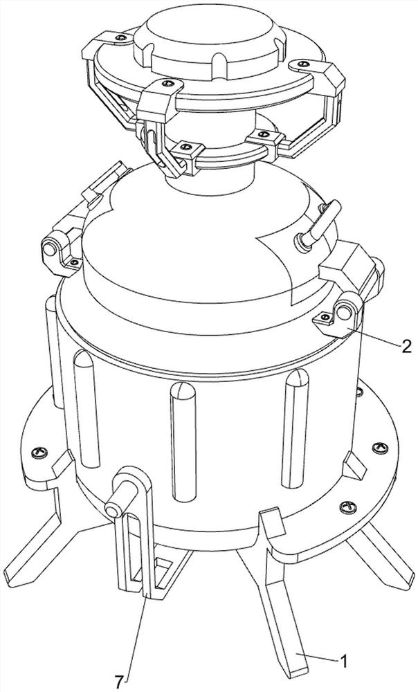
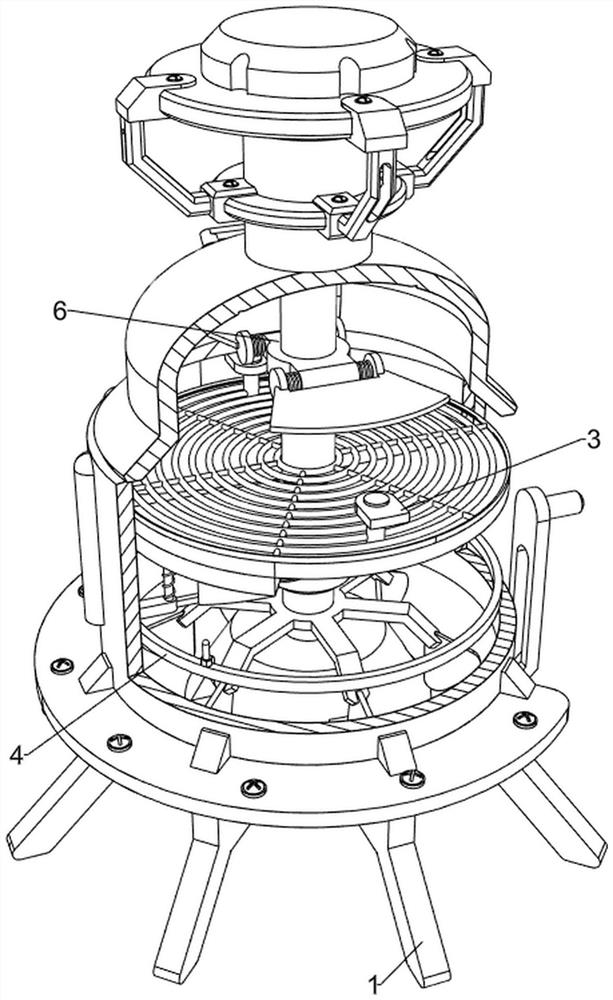
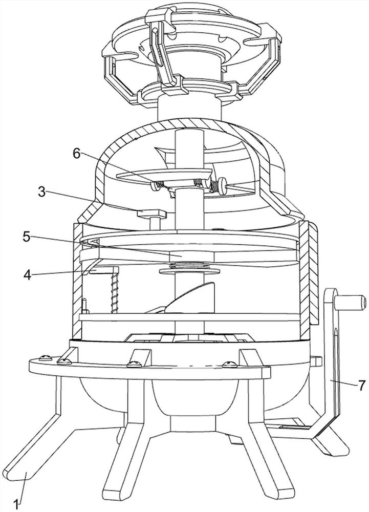
[0036] A compound oil-phase reactor stirring device, such as Figure 1-7 As shown, it includes a support base 1, a material cylinder 11, a fixing frame 12, a motor 13, a first rotating rod 14, a stirring paddle 15, an opening and closing mechanism 2 and a heating mechanism 3. The upper side of the support base 1 is connected with a material cylinder through bolts. 11. The material barrel 11 can be used to place the composite oil phase. The upper left and right sides of the material barrel 11 are provided with feeding ports. The upper side of the material barrel 11 is connected with a fixing frame 12 by bolts. The fixing frame 12 is installed with a motor 13 by bolts. , the output shaft of the motor 13 is provided with a first rotating rod 14, the first rotating rod 14 is rotatably connected with the material cylinder 11, the rotation of the output shaft of the motor 13 can drive the first rotating rod 14 to rotate, and the lower part of the first rotating rod 14 is provided wit...

Embodiment 2

[0041] On the basis of Example 1, as figure 2 , image 3 , Figure 8 and Figure 9 As shown, it also includes an inner wall scraping mechanism 4 capable of scraping off the composite oil phase liquid attached to the inner wall of the material cylinder 11. The inner wall scraping mechanism 4 includes a third fixing block 40, a guide rod 41, a connecting block 42, a spring 43. The scraper 44, the contact rod 45 and the rotating block 46, a third fixing block 40 is arranged on the inner wall of the front side of the material cylinder 11, a guide rod 41 is arranged on the lower side of the third fixing block 40, and the guide rod 41 is slidably connected with a connection Block 42, the guide rod 41 can guide the connecting block 42, a spring 43 is arranged between the upper side of the connecting block 42 and the lower side of the third fixing block 40, the spring 43 is wound on the surface of the guide rod 41, and the spring 43 can make The connecting block 42 moves and reset...


PUM


Abstract

The invention relates to a stirring device, in particular to a stirring device of a compound oil phase reaction kettle. The technical problem is to provide the stirring device of the compound oil phase reaction kettle, which can shield a feed port so as to improve the safety coefficient in the heating process. A composite oil phase reaction kettle stirring device comprises a supporting base, a material barrel, a fixing frame, a motor and the like, the material barrel is arranged on the upper side of the supporting base, the fixing frame is arranged on the upper side of the material barrel, and the motor is arranged on the fixing frame. The rotary cover is opened by rotating towards the outer side, then a compound oil-phase raw material is poured onto the heating pipe by people, then the motor and the heating pipe are started, the compound oil-phase raw material is heated and evaporated by the heating pipe, and the evaporated compound oil-phase liquid can be automatically stirred by rotating the stirring paddle.

Description

technical field [0001] The invention relates to a stirring device, in particular to a stirring device for a composite oil-phase reaction kettle. Background technique [0002] The reaction kettle is a container with physical or chemical reaction, with heating, evaporation, cooling and low-speed mixing functions; the composite oil phase is made of composite wax and composite emulsifier technology and adding various additives, which can be used in emulsification. It is directly used in the production of explosives, and the composite oil phase needs to be processed with a reaction kettle before it is used, and the stirring efficiency of the existing reaction kettle is low when it is heated. [0003] The application patent number is CN201721638105.5 An emulsion explosive compound oil-phase reaction kettle stirring device, including a tank body, a motor and a first blade, the upper end of the left side wall of the tank body is connected with a liquid inlet pipe, and the liquid inl...

Claims


Application Information

Patent Timeline
Patent Type & Authority Applications(China)
IPC IPC(8): B01J19/18B01J4/00B01F27/90B01F35/93B01F35/45B01F35/12B01F35/71B01F35/60B01F35/75
CPCB01J19/18B01J4/001B01J2204/002B01J2204/005
Inventor 高晶李宝林王小龙叶道源黄小林
Owner FUZHOU GUOTAI COMPOSITE MATERIAL CO LTD
Learn More