Waste exhibition appliance recovery processing equipment and recovery processing method

A technology of recycling and display tools, applied in grain processing, solid waste removal, etc., can solve problems such as hidden safety hazards, flying fragments, single crushing method, etc., to improve crushing effect, improve torque strength, and avoid breakage. Effect

Pending Publication Date: 2022-07-29
宿州世纪华悦展具制作有限公司
7 Cites 0 Cited by

AI-Extracted Technical Summary

Problems solved by technology

[0005] The main purpose of the present invention is to solve the problems in the prior art that the working area is more exposed, fragments are likely to fly o...

Abstract

The invention discloses waste exhibition appliance recycling equipment and a recycling method, and belongs to the technical field of waste recycling, the waste exhibition appliance recycling equipment comprises a material box, a conveying assembly and a crushing assembly, the conveying assembly and the crushing assembly are arranged at the top of the material box, the crushing assembly comprises four lower jaw frames and side shafts fixedly connected between the lower jaw frames, and the outer walls of the side shafts are rotationally connected with two upper jaw frames; and a cover plate is fixedly connected between the two upper jaw frames. The conveying assembly and the crushing assembly are arranged, the conveying assembly conveys waste plates to the crushing assembly area, the crushing assembly depends on a jaw type structure, the plates are pressed while the plates are rotationally crushed, the crushing effect is improved, meanwhile, crushed materials are directly fed to the position below the device, the crushed materials are prevented from collapsing and flying, and the crushing efficiency is improved. And the conveying assembly is adjacent to the crushing assembly, and when crushing is executed, subsequent parts of the plates are limited by the conveying assembly, edge warping and collision are avoided, meanwhile, it is guaranteed that the plates are crushed in order, and a conveying channel is prevented from being blocked.

Application Domain

Technology Topic

Image

  • Waste exhibition appliance recovery processing equipment and recovery processing method
  • Waste exhibition appliance recovery processing equipment and recovery processing method
  • Waste exhibition appliance recovery processing equipment and recovery processing method

Examples

  • Experimental program(1)

Example Embodiment

[0030] In order to make the technical solution of the present invention clearer and clearer to those skilled in the art, the present invention will be described in further detail below with reference to the embodiments and accompanying drawings, but the embodiments of the present invention are not limited thereto.
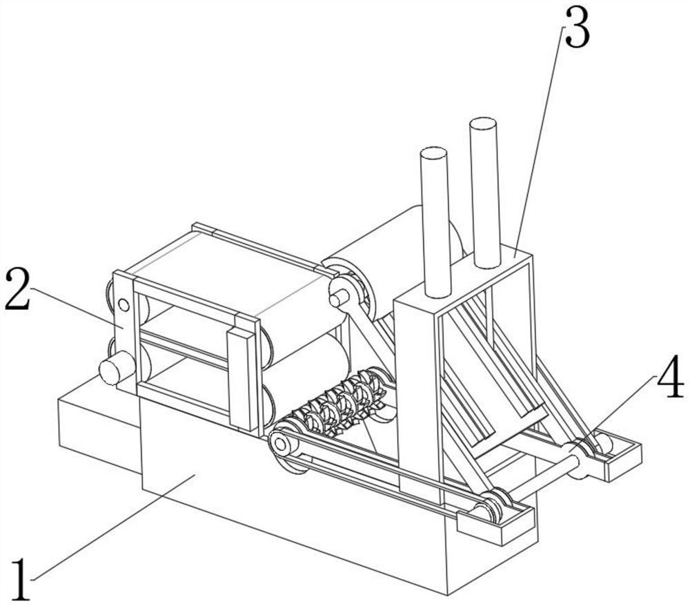
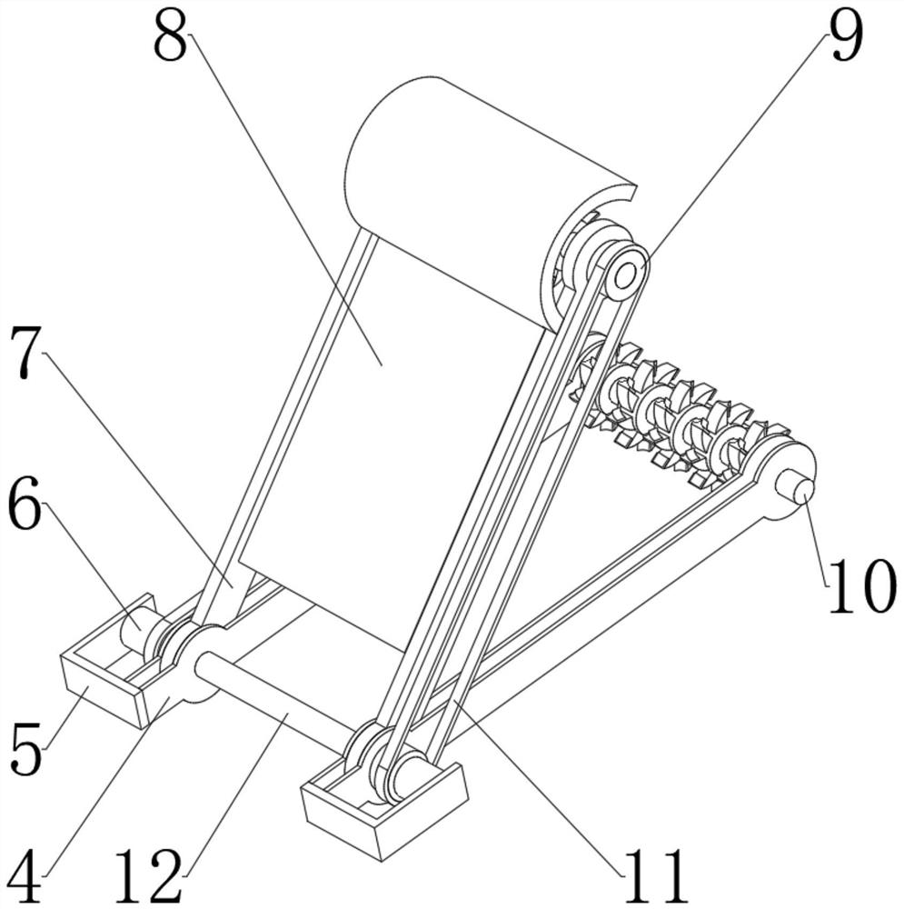
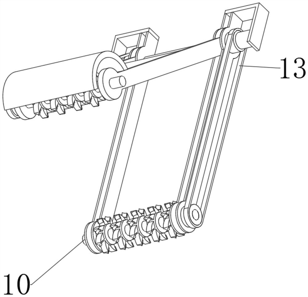
[0031] like Figure 1-Figure 8 As shown, the waste display equipment recycling and processing equipment provided in this embodiment includes a material box 1 and a conveying assembly and a crushing assembly arranged on the top of the material box. The crushing component relies on the jaw structure. While rotating and crushing the plate, it presses the plate to improve the crushing effect, and at the same time directly sends the crushed material to the bottom of the device to avoid the crushed material from collapsing and causing pollution around the device. The crushing components are adjacent to each other. When performing crushing, the subsequent part of the plate will be limited by the conveying component to avoid edge warping and impact, and at the same time ensure the orderly crushing of the plate to avoid blockage of the conveying channel; the crushing component includes four lower jaw frames 4 and fixed Connected to the side shaft 12 therebetween, the outer wall of the side shaft 12 is rotatably connected with two upper jaw frames 7, a cover plate 8 is fixedly connected between the two upper jaw frames 7, and one end of the upper jaw frame 7 and the lower jaw frame 4 is provided with a mandrel 10. The outer walls of the two mandrels 10 are respectively fixed and connected with staggered runners 14. The outer walls of the runners 14 are provided with a plurality of indenters 15, one side of the indenter 15 is provided with a knife block 16, and the upper jaw frame 7 is arranged on the two lower jaw frames. 4, one end of the mandrel 10 is provided with a pulley, one side of the lower jaw frame 4 is provided with a bracket 5, one side of the bracket 5 is provided with a power motor 6, and the outer wall of the output shaft of the power motor 6 is provided with a pulley 9. The upper jaw frame 7 can rotate around the side shaft 12, the power motor 6 is activated, the pulley 9 is driven to rotate through the relevant components, and the mandrel 10 is rotated, and the outer wall of the mandrel 10 is provided with staggered runners 14, which can rotate the plate Pressing is performed, and when the mandrel 10 rotates, the indenter 15 and the cutter block 16 are driven to rotate, and the surface of the plate is crushed. At the same time, the cover plate 8 can prevent the waste from flying out, protecting the device and the operator, and the setting of the indenter 15 The torque strength can be improved to avoid breakage, and at the same time, the relative movement of the upper jaw frame 7 and the lower jaw frame 4 can be used to perform high-frequency compression on the plate to accelerate its breaking.
[0032] In this embodiment, as Figure 1-Figure 5 , Figure 8 As shown, one end of the power motor 6 and the mandrel 10 is provided with a stabilizing belt 13, and is provided on the side of the lower jaw frame 4; the other power motor 6 and one end of the mandrel 10 is provided with a swing belt 11, and the swing belt 11 is provided on the One side of the upper jaw frame 7; one side of the cover plate 8 is provided with a protective cover adapted to the runner 14, and the lower jaw frame 4 is fixedly connected to the top of the material box 1; The cylinder 26, the outer wall of the piston rod of the adjusting cylinder 26 is provided with a sliding shaft 27; the top of the cover plate 8 is provided with a guide block 28, the bottom end of the sliding shaft 27 is set to a T-shaped structure, and the inner wall of the guide block 28 is provided with a sliding shaft 27. Equipped with T-slot. By arranging the stabilizing belt 13 and the swinging belt 11, the torque transmission between the power motor 6 and the mandrel 10 can be maintained at all times, and the cover plate 8 is used to provide a protective function, while relying on the protective cover to clamp the upper runner 14, At the same time, under the adjustment of the adjusting cylinder 26, the sliding shaft 27 is driven to move in the T-shaped groove inside the guide block 28, thereby driving the cover plate 8 and the entire upper jaw frame 7 to rotate to provide pressing force.
[0033] In this embodiment, as figure 1 , Image 6 and Figure 7As shown, the conveying assembly includes a conveying frame 2 fixedly connected to the top of the material box 1 and a conveying motor 17 arranged on one side of the conveying frame 2; the conveying frame 2 is provided with a plurality of hinges 20, and the outer walls of the hinges 20 are fixedly connected with rollers 21. The outer walls of the two rollers 21 on the same plane are provided with a conveying belt 19; the output shaft of the conveying motor 17 is fixedly connected to one of the shafts 20, and a communication box 18 is provided on one side of the conveying frame 2, and the interior of the communication box 18 is provided with two. A chain drive module connected with a hinge shaft 20; one side of the material box 1 is provided with a cabinet door 25, the other side is provided with a discharge cylinder 23, and the output end of the discharge cylinder 23 is provided with a push block 22 with a triangular structure. 1 is provided with a maintenance slot 24 at the top. By setting the conveying assembly, the conveying motor 17 is activated to drive the shaft 20 to rotate, the roller 21 is rotated to drive the conveying belt 19 to move, and at the same time, the two conveying belts 19 are driven to rotate in the same direction by the connecting box 18, so that the plate is conveyed to the inside, and The chain rotation module is used to keep the two conveyor belts 19 rotating synchronously. Further, after the crushed material enters the material box 1, the discharge cylinder 23 is activated to drive the push block 22 to push the material out. The cabinet door 25 can close the material box 1 under its own weight, and the cabinet door 25 can be rotated and opened to facilitate the release of materials.
[0034] In this embodiment, as Figure 1-Figure 8 As shown in the figure, the recycling and processing method of the waste exhibition equipment recycling and processing equipment includes the following steps: Step 1: The power motor 6 is started, and the pulley 9 is driven to rotate through the relevant components, and the mandrel 10 is rotated, and the outer wall of the mandrel 10 is provided with staggered The arranged runners 14 can press and fit the plates; Step 2: When the mandrel 10 rotates, it drives the indenter 15 and the cutter block 16 to rotate, and the surface of the plate is broken, and the cover plate 8 can prevent the waste chips from flying out; step 3: Using the relative movement of the upper jaw frame 7 and the lower jaw frame 4, the plate can be compressed at high frequency to accelerate its breaking.
[0035] In this embodiment, as Figure 1-Figure 8 As shown, the working process of the waste display equipment recycling and processing equipment provided in this embodiment is as follows:
[0036] Step 1: The power motor 6 is started, and the pulley 9 is driven to rotate through the relevant components, and the mandrel 10 is rotated, and the outer wall of the mandrel 10 is provided with runners 14 arranged in a staggered manner, which can press the plates;
[0037] Step 2: When the mandrel 10 rotates, the indenter 15 and the cutter block 16 are driven to rotate, and the surface of the plate is broken, and the cover plate 8 can prevent the waste chips from flying out;
[0038] Step 3: Using the relative movement of the upper jaw frame 7 and the lower jaw frame 4, the plate can be compressed at high frequency to accelerate its breaking.
[0039] To sum up, in this embodiment, according to the waste exhibition equipment recycling and processing equipment and recycling processing method of this embodiment, by setting up a conveying assembly and a crushing assembly, the conveying assembly conveys the waste plates to the area of ​​the crushing assembly, and the crushing assembly relies on the jaw structure. , While rotating the crushing plate, the plate is pressed to improve the crushing effect, and the crushed material is directly sent to the bottom of the device to avoid the collapse of the crushed material and cause pollution around the device, and the conveying component is adjacent to the crushing component. When performing crushing, the subsequent part of the plate will be limited by the conveying component to avoid edge warping and impact, and at the same time ensure that the plate is crushed in an orderly manner and avoid blockage of the conveying channel; the upper jaw frame 7 can rotate around the side shaft 12, and the power motor 6 is activated. , the pulley 9 is driven to rotate by the relevant components, and the mandrel 10 is rotated, and the outer wall of the mandrel 10 is provided with staggered runners 14, which can press the plates, and when the mandrel 10 rotates, it drives the indenter 15 and The cutter block 16 rotates to smash the surface of the plate, and the cover plate 8 can prevent the waste chips from flying out, protecting the device and the operator, and the setting of the indenter 15 can improve its torque strength and avoid breakage. At the same time, the upper jaw frame 7 and the lower jaw are used The relative movement of the frame 4 can carry out high-frequency compression on the plate and accelerate its breaking;
[0040] By arranging the stabilizing belt 13 and the swinging belt 11, the torque transmission between the power motor 6 and the mandrel 10 can be maintained at all times, and the cover plate 8 is used to provide a protective function, while relying on the protective cover to clamp the upper runner 14, At the same time, under the adjustment of the adjusting cylinder 26, the sliding shaft 27 is driven to move in the T-shaped groove inside the guide block 28, thereby driving the cover plate 8 and the entire upper jaw frame 7 to rotate to provide pressing force;
[0041] By setting the conveying assembly, the conveying motor 17 is activated to drive the shaft 20 to rotate, the roller 21 is rotated to drive the conveying belt 19 to move, and at the same time, the two conveying belts 19 are driven to rotate in the same direction by the connecting box 18, so that the plate is conveyed to the inside, and The chain rotation module is used to keep the two conveyor belts 19 rotating synchronously. Further, after the crushed material enters the material box 1, the discharge cylinder 23 is activated to drive the push block 22 to push the material out. The cabinet door 25 can close the material box 1 under its own weight, and the cabinet door 25 can be rotated and opened to facilitate the release of materials.
[0042] The above are only further embodiments of the present invention, but the protection scope of the present invention is not limited to this. Equivalent replacements or changes all belong to the protection scope of the present invention.

PUM

no PUM

Description & Claims & Application Information

We can also present the details of the Description, Claims and Application information to help users get a comprehensive understanding of the technical details of the patent, such as background art, summary of invention, brief description of drawings, description of embodiments, and other original content. On the other hand, users can also determine the specific scope of protection of the technology through the list of claims; as well as understand the changes in the life cycle of the technology with the presentation of the patent timeline. Login to view more.

Similar technology patents

Back crushing device

Owner:克拉斯自行式收获机械有限公司

Classification and recommendation of technical efficacy words

  • Improve the crushing effect
  • Prevent crash

High-temperature melting equipment for preparing nano glass powder

InactiveCN106348571AImprove the crushing effectSpeed up the fallCharging furnaceGlass furnace apparatusConductor CoilNanotechnology
Owner:徐州启迪双创科技企业孵化器有限公司

Coal briquette rapid crushing device

InactiveCN108097354AImprove the crushing effectAchieve rapid crushing effectGrain treatmentsCoalCam
Owner:ZHENGZHOU YUANRAN BIOLOGY TECH CO LTD

High-speed leftover fabric crushing device

Owner:HUBEI TIANYUN NOISE REDUCTION & ANTIVIBRATION NEW MATERIAL
Why Eureka
Try Eureka