Base metal particle forming equipment

A particle forming and base metal technology, which is applied in the field of base metal particle forming equipment, can solve the problems of low processing precision, large particle size, unevenness, etc., and achieve the effects of fine forming size, increased centrifugal compression, and expanded application range

Pending Publication Date: 2022-07-29
SUZHOU VOCATIONAL UNIV
View PDF0 Cites 0 Cited by
  • Summary
  • Abstract
  • Description
  • Claims
  • Application Information

AI Technical Summary

Problems solved by technology

[0005] The purpose of the present invention is to solve the following problems in the prior art: there are many methods for preparing metal particles, including chemical, physical, electrical and other methods, and each method has its own advantages. The particle method is the simplest, and the processing efficiency is very high, but its processing accuracy is low, the particle size is large, and uneven, resulting in less use of this method

Method used


Image

  • Base metal particle forming equipment
  • Base metal particle forming equipment
  • Base metal particle forming equipment

Examples


Embodiment 1

[0034] The liquid metal is formed into splash droplets by rotating centrifugal method, and the droplets are refined with high-frequency vibration. The specific operations are as follows:

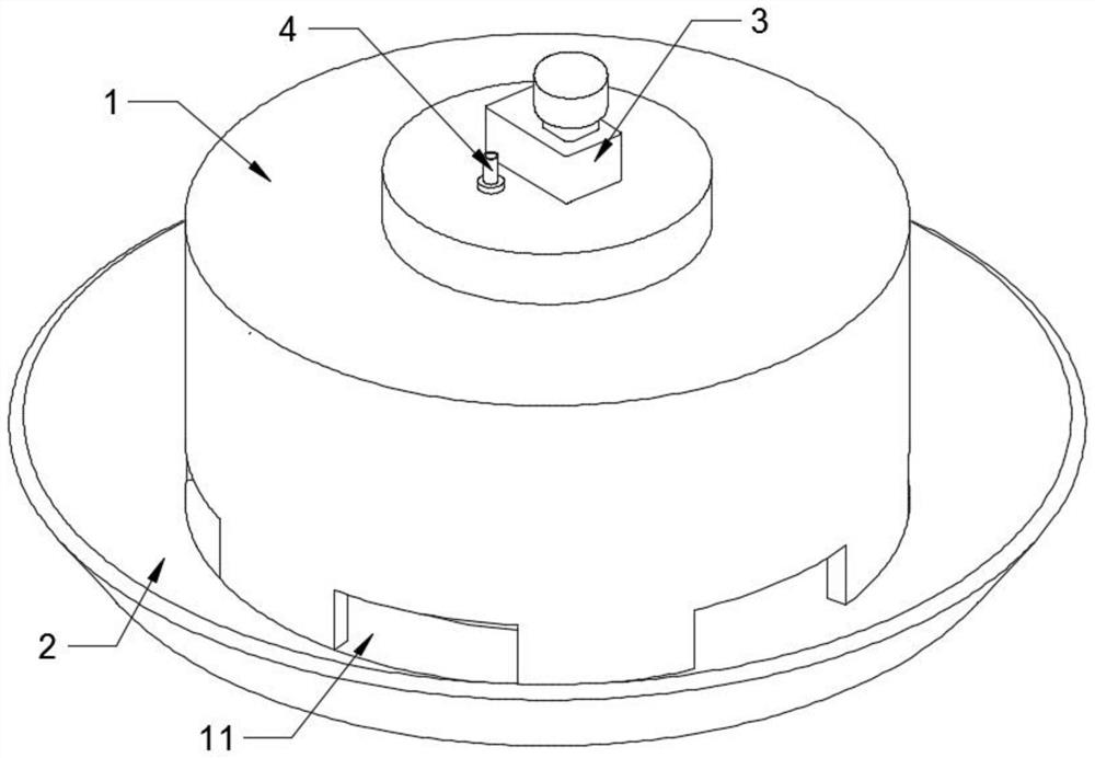
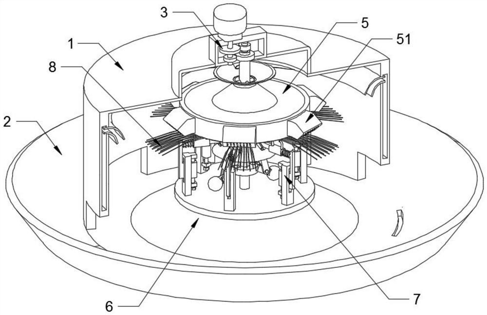
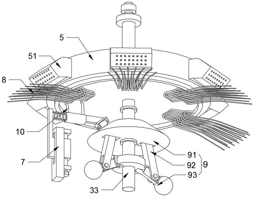
[0035] like figure 1 , figure 2 and image 3 As shown, a base metal particle forming equipment includes a forming chamber 1 with a driving device 3 at the top, a centrifugal disc 5 connected to the driving device 3 is arranged inside the forming chamber 1, the centrifugal disc 5 is suspended, and the centrifugal disc 5 includes a centrifugal chamber 53. The edge of the centrifugal chamber 53 passes through a plurality of end shells 51, the end surface of the end shell 51 has a number of pores, and the bottom of the end shell 51 is provided with a number of elastic steel needles 8 extending radially along the centrifugal chamber 53. The end is fixedly connected to the centrifugal chamber 53 , a lever 10 connected to the molding chamber 1 is arranged below the elastic steel needle 8 , the l...


PUM


Abstract

The invention relates to the technical field of base metal particle manufacturing, in particular to base metal particle forming equipment which comprises a forming chamber with a driving device arranged at the top, a centrifugal disc connected with the driving device is arranged in the forming chamber and suspended and comprises a centrifugal chamber, and the edge of the centrifugal chamber penetrates through a plurality of end shells. A plurality of fine holes are formed in the end face of the end shell, a plurality of elastic steel needles extending in the radial direction of the centrifugal chamber are arranged at the bottom of the end shell, the ends of the elastic steel needles are fixedly connected with the centrifugal chamber, a deflector rod connected with the forming chamber is arranged below the elastic steel needles and makes contact with the elastic steel needles, and a feeding pipe for injecting molten metal into the centrifugal chamber penetrates through the top of the forming chamber. Flying-out metal liquid drops are conducted through the elastic steel needle arranged at the end of the end shell, the rotating elastic steel needle is shifted through the shifting rod to generate high-frequency vibration, the metal liquid drops are further crushed and refined, and the forming size of metal particles is finer.

Description

technical field [0001] The present invention relates to the technical field of base metal particle manufacture, in particular to a base metal particle forming equipment. Background technique [0002] The use of metal particles to prepare semi-finished mechanical parts is a relatively mature processing method. The semi-finished parts prepared by using metal particles have more prominent advantages than ingot semi-finished products. The structure and properties of the prepared granular materials are also different from those prepared by traditional standard processes. , the mechanical properties of the parts have been significantly improved, and the semi-finished products are more representative. [0003] The newly developed particle forming process uses the particles formed by the solidification of metal droplets under high temperature cooling conditions as blanks. The loose substances with a particle size of 0.5-10 mm obtained when the alloy melt is rapidly crystallized are ...

Claims


Application Information

Patent Timeline
Patent Type & Authority Applications(China)
IPC IPC(8): B22F9/10
CPCB22F9/10
Inventor 王效宇闫梦强万长东陆建康浦京
Owner SUZHOU VOCATIONAL UNIV
Why Eureka
Try Eureka