Eureka AIR delivers breakthrough ideas for toughest innovation challenges, trusted by R&D personnel around the world.

Fixed-length shearing device for rod and wire production

A technology of cutting to length, rod and wire, applied in the direction of shearing device, accessory device of shearing machine, shearing machine equipment, etc. question

Pending Publication Date: 2022-07-29
XINJIANG BAYI IRON & STEEL
View PDF0 Cites 1 Cited by
  • Summary
  • Abstract
  • Description
  • Claims
  • Application Information

AI Technical Summary

Problems solved by technology

[0003] During the use of the existing cut-to-length shearing device for the production of rods and wires, the rods and wires are cut to length by moving the position of the baffle. The rods and wires in contact with the baffle are still moving, causing the rods and wires to exert greater pressure on the baffle, making the connection between the baffle and the connecting seat loose, reducing the service life of the baffle; secondly, the existing rods and wires During the use of the fixed-length shearing device for production, when the cutting knife cuts the rod and wire, the rod and wire are prone to jumping, which makes the stability poor and reduces the flatness of the shearing surface; resulting in the final finished rod The ends of the bales are uneven, and the change of the finished product rate is uncontrollable; and during the use of the existing cut-to-length shearing device for rod and wire production, a large amount of small impurities will be generated during cutting, and it is relatively difficult for the staff to collect and clean these small impurities. Trouble, increase the work intensity of the staff

Method used


Image

  • Fixed-length shearing device for rod and wire production
  • Fixed-length shearing device for rod and wire production
  • Fixed-length shearing device for rod and wire production

Examples


Embodiment Construction

[0015] The present invention will be further described below in conjunction with the accompanying drawings:

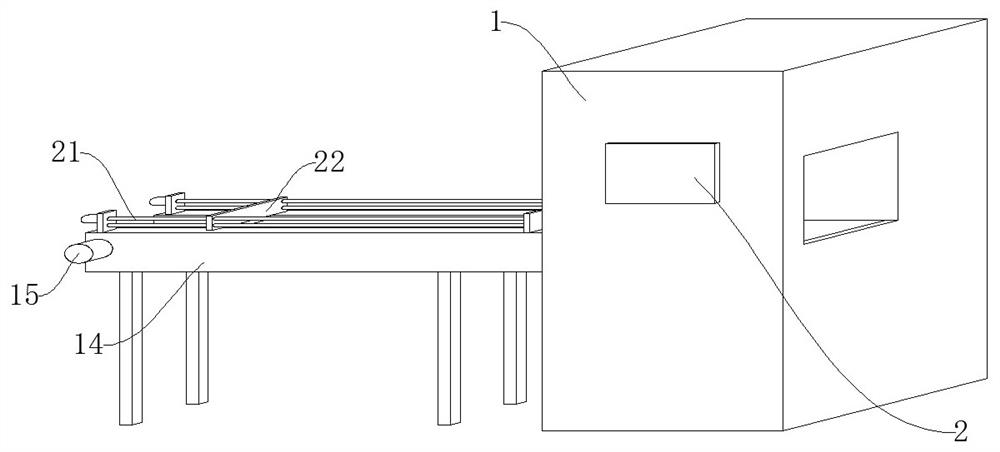
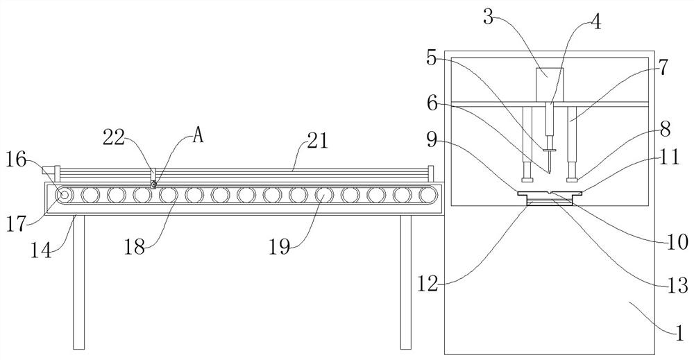
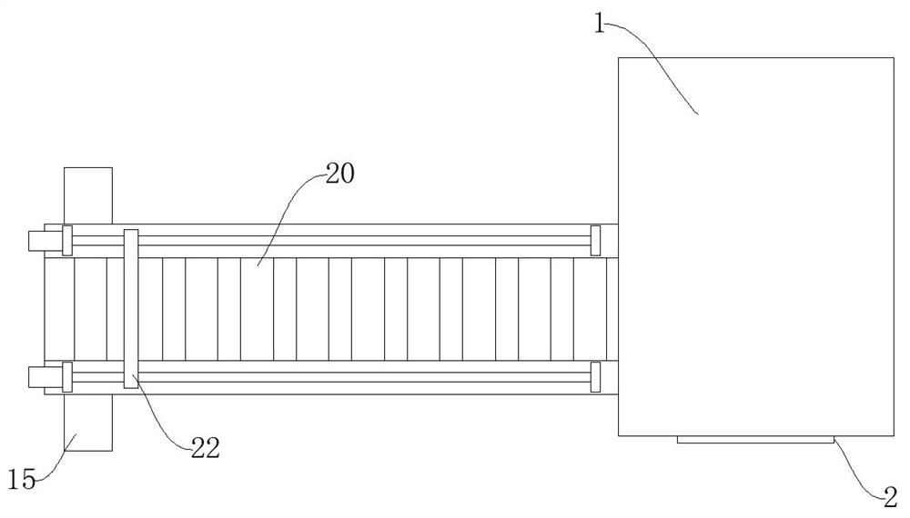
[0016] like Figure 1-Figure 4 As shown, a fixed-length shearing device for bar and wire production includes a body 1, a support frame 14 and an electric sliding rail 21. An operation panel 2 is installed on one side of the body 1, and the staff can use the operation panel 2 to control the device. A hydraulic cylinder 3 is fixed on the upper part of the body 1. The hydraulic cylinder 3 can drive a piston rod 4 to move. A piston rod 4 is installed at the bottom of the hydraulic cylinder 3. The piston rod 4 can drive the mounting plate 5 to move. The bottom of the piston rod 4 is fixed with a mounting plate. 5. The mounting plate 5 can be installed with a cutting knife 6, and the bottom of the mounting plate 5 is connected with a cutting knife 6. The cutting knife 6 can cut the rod and wire, and both sides of the cutting knife 6 are provided with electric push rods 7, T...


PUM


Abstract

An operation panel is installed on one side of a machine body, a hydraulic cylinder is fixed to the upper portion in the machine body, a piston rod is installed at the bottom of the hydraulic cylinder, a mounting plate is fixed to the bottom of the piston rod, a cutting knife is connected to the bottom of the mounting plate, and electric push rods are arranged on the two sides of the cutting knife. A cutting seam is formed in the middle of the upper portion of the supporting seat, a cavity is formed in the supporting seat, a bearing plate is fixed to the middle of the interior of the supporting seat, a magnetic suction plate is installed at the top of the bearing plate, a supporting frame is arranged on the other side of the machine body, a motor is installed on one side of the supporting frame, and a connecting shaft is installed at one end of the motor; a rotating wheel is fixed to one end of the connecting shaft, a rotating belt is connected to the rotating wheel, and a transmission wheel is connected to the rotating belt. The rod and wire cutting device can prevent rods and wires from shaking during cutting, stability is improved, and then the flatness of a cut face is improved.

Description

technical field [0001] The invention relates to a fixed-length shearing device for bar and wire production. Background technique [0002] Rods and wires are divided into ordinary rods and wires and special steel rods and wires, with specifications: 9-50mm, 50-100mm, 100-300mm; wires are divided into wire rods and special wires, with specifications: 5-10mm, rods and wires have small cross-sections, Large length requires higher dimensional accuracy and surface quality. [0003] In the process of using the existing fixed-length shearing device for bar and wire production, the rod and wire are fixed to length by moving the position of the baffle. The rods and wires in contact with the baffles continue to move, causing the rods and wires to exert greater pressure on the baffles, making the connection between the baffles and the connecting seat loose, reducing the service life of the baffles; secondly, the existing rods and wires During the use of the fixed-length shearing devic...

Claims


Application Information

Patent Timeline
Patent Type & Authority Applications(China)
IPC IPC(8): B23D31/00B23D33/00B23D33/02B23D33/08
CPCB23D31/00B23D33/006B23D33/00B23D33/02B23D33/08
Inventor 张钟胜郭守军毕健
Owner XINJIANG BAYI IRON & STEEL
Why Eureka
Eureka Blog
Learn More