Machining tool and machining method for shell and inner bottom of injector

A processing method and injector technology, which are used in manufacturing tools, other manufacturing equipment/tools, etc., to achieve the effects of improving processing accuracy, improving processing qualification rate, and improving clamping efficiency

Pending Publication Date: 2022-07-29
XIAN SPACE ENGINE CO LTD
View PDF0 Cites 0 Cited by
  • Summary
  • Abstract
  • Description
  • Claims
  • Application Information

AI Technical Summary

Problems solved by technology

[0003] The technical problem to be solved by the present invention is: to overcome the deficiencies of the prior art, to solve the problem that both the l

Method used


Image

  • Machining tool and machining method for shell and inner bottom of injector
  • Machining tool and machining method for shell and inner bottom of injector
  • Machining tool and machining method for shell and inner bottom of injector

Examples


Example Embodiment

[0028] Example 1:

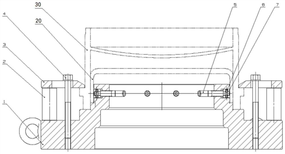
[0029] A processing tool and processing method for an injector housing and an inner bottom, the injector housing 30 and the upper end hole of the inner bottom are welded together when they are coaxial, and the injector housing 30 and the upper end of the inner bottom 20 are welded together. The number of faces is large and the number is the same. This method is to use the same processing procedure to process the upper end faces of the injector housing 30 and the inner bottom 20 respectively when the injector housing 30 and the inner bottom 20 are clamped at one time to ensure the positioning accuracy. The relative positional accuracy of the injector housing 30 and the hole in the inner bottom 20 can be achieved.

[0030] The processing tool includes a positioning plate 1, a spacer 2, a pressure plate 3, a first screw 4, a second screw 5, a cylindrical end set screw 6, and an expansion ring 7. The processing tool realizes the connection between the injector ...

Example Embodiment

[0044] Example 2:

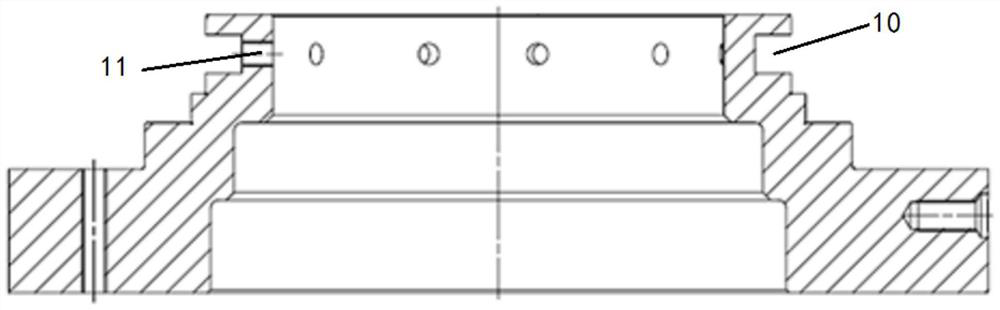
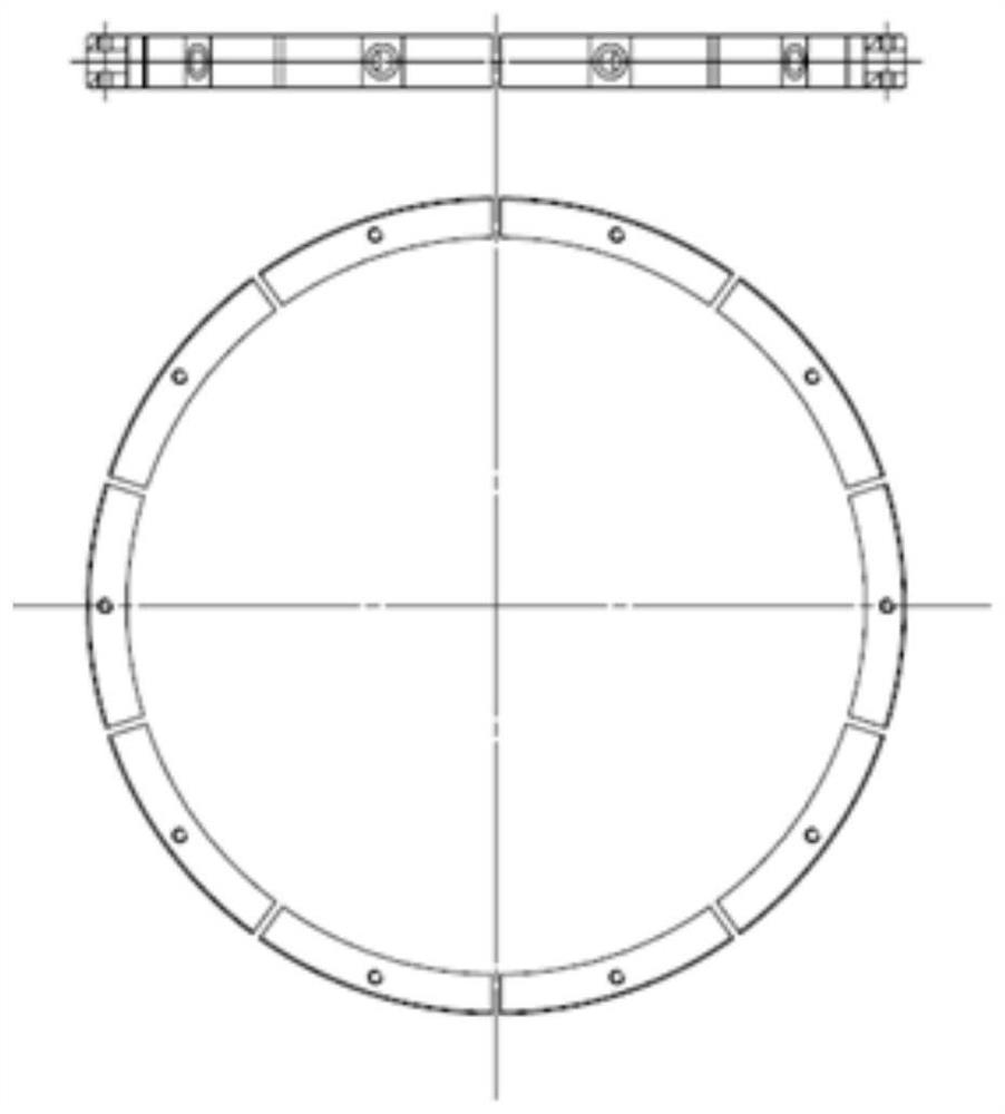
[0045] A processing tool for an injector housing and an inner bottom, comprising a positioning plate 1, a spacer 2, a pressure plate 3, and a plurality of ring-shaped expansion rings 7;

[0046] The positioning plate 1 is cylindrical as a whole, the outer surface is stepped, and the outer envelope gradually shrinks from one end to the other end. An annular groove 10 is provided on the smallest end, and a hole 11 is arranged in the groove 10. The interior of the positioning plate 1 A through hole is formed along the axial direction; the inner bottom 20 is sleeved on the smallest end of the positioning plate, and the injector housing 30 is sleeved on the positioning plate and the inner bottom 20 at the same time;

[0047] A plurality of expansion rings 7 are located in the groove 10 and abut against the inner circle of the inner bottom 20. By adjusting the position of one or more expansion rings 7, the outer circle of the inner bottom 20 can reach a predeterm...


PUM


Abstract

A machining tool for an injector shell and an inner bottom comprises a positioning disc, a cushion block, a pressing plate and a plurality of expansion rings forming a circular ring. The whole positioning disc is columnar, the outer surface of the positioning disc is in a step shape, the outer envelope of the positioning disc is gradually reduced from one end to the other end, an annular groove is formed in the minimum end, a hole is formed in the groove, and a through hole is formed in the positioning disc in the axis direction. The inner bottom is sleeved on the smallest end of the positioning disc, and the injector shell is sleeved on the positioning disc and the inner bottom at the same time; the multiple expansion rings are located in the groove and abut against the inner circle of the inner sole, and the outer circle of the inner sole reaches the preset position by adjusting the position of one or more expansion rings; the cushion block is located between the positioning disc and the pressing plate and used for supporting the pressing plate, the pressing plate is connected with the positioning disc and then presses the injector shell, and the position of the injector shell and the position of the inner bottom are fixed. According to the method, the problems that holes need to be machined before the injector shell and the inner bottom of the liquid rocket engine are welded, and the hole position precision is guaranteed are solved.

Description

technical field [0001] The invention relates to a processing tool and a processing method for an injector casing and an inner bottom, namely a processing tool and a processing method for a liquid rocket engine injector casing and an inner bottom hole, belonging to the technical field of liquid rocket engines . Background technique [0002] The injector housing and inner bottom are an integral part of the liquid rocket engine and provide the main components for rocket power. Since the number of holes on the shell and the inner bottom is very large, and the shell and the inner bottom need to be processed before welding, after the machining is completed, the shell and the inner bottom need to be assembled and welded; when assembling and welding, it is necessary to ensure that the shell and the inner bottom The holes processed at the bottom are coaxial. Due to the machining position error and the large number of holes, it is difficult to ensure the relative position of the hole...

Claims


Application Information

Patent Timeline
IPC IPC(8): B23P23/04B23P15/00
CPCB23P23/04B23P15/00
Inventor 陈磊卢博张和平刘赫刘广续何小虎刘超智李宝强
Owner XIAN SPACE ENGINE CO LTD
Why Eureka
Try Eureka