Workbench of vertical turning machining center
A machining center and workbench technology, which is applied to metal processing equipment, metal processing machinery parts, manufacturing tools, etc., can solve the problems of inconvenient disassembly and maintenance of the workbench of vertical turning machining centers, achieve smooth movement, improve processing efficiency, reduce The effect of the overall area
- Summary
- Abstract
- Description
- Claims
- Application Information
AI Technical Summary
Problems solved by technology
Method used
Image
Examples
no. 1 example
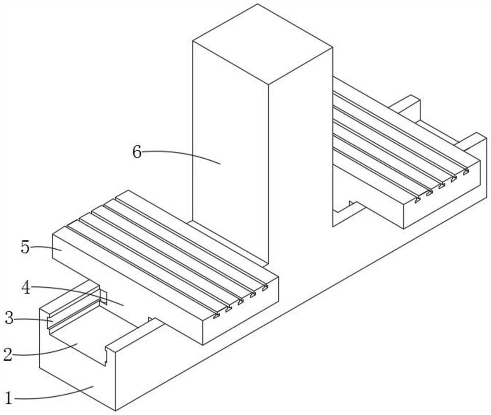
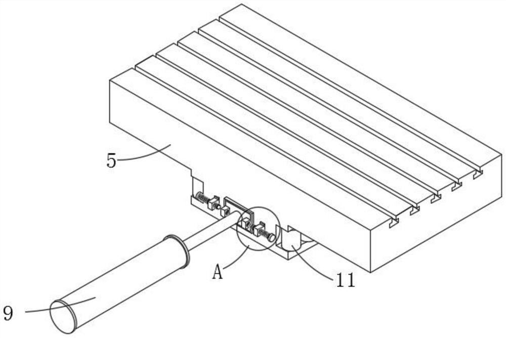
[0029] see Figure 1 to Figure 6 , in a specific embodiment, the workbench of the vertical turning machining center includes: a workbench body 5; a switch base 1, the top of the switch base 1 is in contact with the bottom of the workbench body 5, and the switch base 1 is provided with a switch slide Slot 2, the top of the switching base 1 is provided with a column 6; the sliding part 4, the sliding part 4 is arranged on the worktable body 5, the sliding part 4 is engaged in the interior of the switching chute 2, and the sliding part 4 and the switching chute 2 A sliding mechanism is provided; the first cavity 8 is arranged inside the switching base 1; the connecting mechanism is connected with the worktable body 5; wherein, the connecting mechanism includes: a connecting plate 13, the connecting plate 13 and the driving cylinder 9 The output end is fixedly connected and fits with the surface of the workbench body 5; the locking block 12, the locking block 12 is integrally form...
no. 2 example
[0036] In a specific embodiment, the sliding mechanism includes: a limiting groove 3, which is provided on the inner wall of the sliding mechanism; a second accommodating groove 19, which is provided on the inner wall of the sliding part 4; a second roller 11. The second roller 11 is arranged on the inner wall of the second accommodating groove 19, and the surface of the second roller 11 is in contact with the inner wall of the limiting groove 3; wherein, an elastic component is provided between the second roller 11 and the second accommodating groove 19 .
[0037] The limit slot 3 is set on the inner wall of the switching chute 2, and the inner walls on both sides are provided with a limit slot 3. One end of the limit slot 3 is in contact with the column 6, and the other end extends to the outside of the switch base 1, which increases as much as possible. In the moving space of the worktable body 5, the second accommodating groove 19 is provided below the worktable body 5, and ...
no. 3 example
[0041] In a specific embodiment, the elastic component includes: a second cavity 21, the second cavity 21 is provided inside the sliding portion 4, and the spring 18 is fixedly installed in the inside of the second cavity 21; a groove 23, a groove 23 is arranged inside the second accommodating groove 19, the second accommodating groove 19 and the second cavity 21 communicate with each other through the groove 23; the rotating shaft 22, the rotating shaft 22 is rotatably connected with the second roller 11; wherein, one end of the spring 18 is fixed with a stopper The ring 25 is provided with a movable rod 24 on the inner wall of the blocking ring 25 , and the movable rod 24 is rotatably connected with the first end of the rotating shaft 22 .
[0042] A second accommodating groove 19 recessed inward is provided on the side of the worktable body 5 close to the switching chute 2, a part of the second roller 11 is located in the second accommodating groove 19, and a groove 23 is op...
PUM
 Abstract
Description
Claims
Application Information
 - R&D Engineer
- R&D Manager
- IP Professional
- Industry Leading Data Capabilities
- Powerful AI technology
- Patent DNA Extraction
Browse by: Latest US Patents, China's latest patents, Technical Efficacy Thesaurus, Application Domain, Technology Topic, Popular Technical Reports.
© 2024 PatSnap. All rights reserved.Legal|Privacy policy|Modern Slavery Act Transparency Statement|Sitemap|About US| Contact US: help@patsnap.com


