


Quick Research
Generate reliable direction feasibility study reports for your R&D in just a few steps.

Technical Q&A
Discover and master advanced knowledge NOW. Basics, ideas, possibilities, all at once.

Find Solutions
As an expert in R&D theories, this can generate solutions to your technical problems instantly.

Evaluate Feasibility
Analyze your overall solution with one click, know your potential R&D risks in advance.

Monitor Landscape
Get weekly tech updates, stay abreast of the latest tech innovations and key insights.
Liquid ejection head and liquid ejection apparatus
A liquid ejection head and liquid technology, applied in printing and other directions, can solve problems such as easy escape
- Summary
- Abstract
- Description
- Claims
- Application Information
AI Technical Summary
Problems solved by technology
Method used
Image

Examples
Embodiment approach
[0024] 1-1. Overall structure of the liquid ejection device
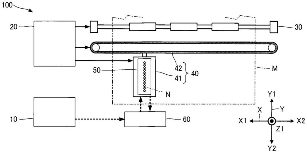
[0025] figure 1 It is a block diagram which shows typically the liquid discharge apparatus 100 which concerns on 1st Embodiment. The liquid discharge apparatus 100 is an ink jet printing apparatus that discharges ink, which is an example of a liquid, onto the medium M as droplets. The medium M is typically printing paper. In addition, the medium M is not limited to printing paper, and may be a printing object of any material such as resin film or cloth, for example.
[0026] like figure 1 As shown, a liquid container 10 for storing ink is installed in the liquid ejecting device 100 . Specific examples of the liquid container 10 include, for example, an ink cartridge that can be attached to and detached from the liquid ejecting device 100 , a pouch-shaped ink bag formed of a flexible film, and an ink tank that can replenish ink. In addition, the kind of ink stored in the liquid container 10 is arbitrary.
[002...
no. 2 approach
[0095] Hereinafter, a second embodiment of the present invention will be described. Elements whose functions and functions are the same as those of the first embodiment in the modes illustrated below will be denoted by the reference numerals used in the description of the first embodiment, and detailed descriptions of them will be appropriately omitted.
[0096] Image 6 It is a cross-sectional view of the liquid ejection head 50A according to the second embodiment. The liquid ejection head 50A is the same as the liquid ejection head 50 of the above-described first embodiment except that the shape of the communication passage Ra1 is different. In addition, although not shown in the figure, the communication passage Ra2 is configured in the same manner as the communication passage Ra1.
[0097] In this embodiment, as Image 6 As shown, the communication passage Ra1 has a shape in which the width gradually decreases toward the Z2 direction when viewed from a cross section per...
no. 3 approach
[0101] Hereinafter, a third embodiment of the present invention will be described. Elements whose functions and functions are the same as those of the first embodiment in the modes illustrated below will be denoted by the reference numerals used in the description of the first embodiment, and detailed descriptions of them will be appropriately omitted.
[0102] Figure 7 It is a cross-sectional view of the liquid ejection head 50B according to the third embodiment. Figure 8 to show schematically Figure 7 A plan view of the flow path of the liquid ejection head 50B shown. The liquid ejection head 50B is the same as the liquid ejection head 50 of the above-described first embodiment except that the communication plate 52B is provided instead of the communication plate 52 . The communication plate 52B is the same as the communication plate 52 except that the shape of the communication passage Ra1 is different.
[0103] like Figure 7 As shown, the communication passage Ra1...
PUM
 Abstract
Description
Claims
Application Information
 - R&D Engineer
- R&D Manager
- IP Professional
- Industry Leading Data Capabilities
- Powerful AI technology
- Patent DNA Extraction
Browse by: Latest US Patents, China's latest patents, Technical Efficacy Thesaurus, Application Domain, Technology Topic, Popular Technical Reports.
© 2024 PatSnap. All rights reserved.Legal|Privacy policy|Modern Slavery Act Transparency Statement|Sitemap|About US| Contact US: help@patsnap.com