
Combined flow plating machine for plating small parts

A combined, flow plating machine technology, applied in the direction of electrolysis components, cells, electrolysis process, etc., can solve the problems of slow electroplating speed, doping more impurities, poor fluidity of the plating solution, etc., to speed up electroplating speed and enhance fluidity , the effect of convenient recycling

Pending Publication Date: 2022-07-29
天津市成吉斯宾科技发展有限公司
View PDF0 Cites 0 Cited by
  • Summary
  • Abstract
  • Description
  • Claims
  • Application Information

AI Technical Summary

Problems solved by technology

[0004] The purpose of the present invention is to provide the flow plating machine of combined plating small piece, to solve the problem that the existing flow plating machine proposed in the above-mentioned background technology is in the process of carrying out electroplating treatment to material, and the fluidity of plating solution is poor, causes electroplating speed to be slow, When the plating solution is repeatedly used many times, it will be doped with more impurities, which will affect the effect of flow plating

Method used


Image

  • Combined flow plating machine for plating small parts
  • Combined flow plating machine for plating small parts
  • Combined flow plating machine for plating small parts

Examples


Embodiment Construction

[0022] In order to have a clearer understanding of the technical features, objects and effects of the present invention, the specific embodiments of the present invention will now be described with reference to the accompanying drawings.

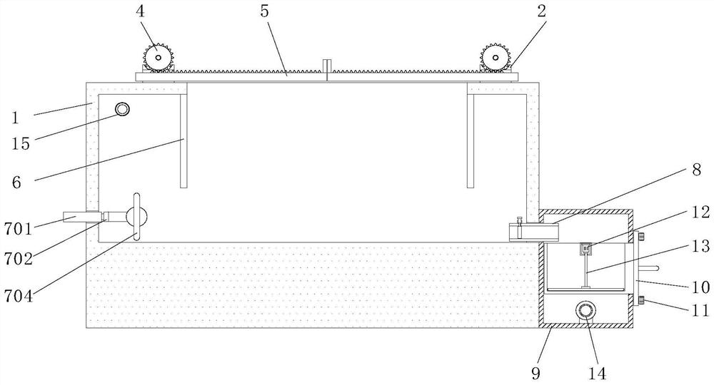
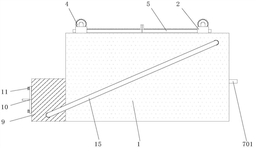
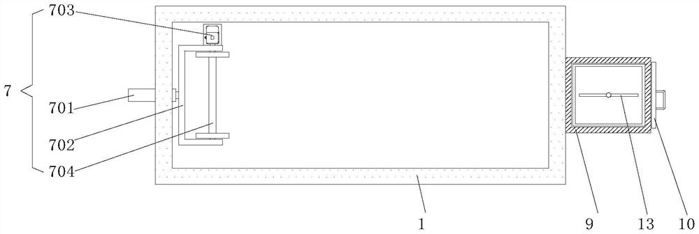
[0023] A preferred embodiment of the combined flow plating machine for plating small parts provided by the present invention is as follows: Figure 1 to Figure 5 As shown, it includes a carrying box 1, a cover plate 5 and a third motor 12. A cover plate 2 is symmetrically fixed on both sides of the top of the carrying box 1, the cover plate 5 penetrates the cover plate 2, and a stopper is symmetrically fixed on both sides of the inner top of the carrying box 1. Plate 6, a push mechanism 7 is fixed on one side of the carrying box 1, an electric liquid outlet valve 8 and a filter box 9 are fixed on the other side of the carrying box 1, and the electric liquid outlet valve 8 is communicated with the filter box 9, The box 1, the cover plate 5 an...


PUM


Abstract

The invention relates to a combined flow plating machine for plating small parts, which comprises a bearing box, a cover plate and a third motor, baffle plates are symmetrically fixed on two sides of the top in the bearing box, a pushing mechanism is fixed on one side of the bearing box, an electric liquid outlet valve and a filter box are fixed on the other side of the bearing box, the electric liquid outlet valve is communicated with the filter box, and the filter box is communicated with the cover plate. A filter box penetrates through one side of the filter box, a scraping rod is rotationally connected to the inner top of the filter box, a liquid pump is fixed to the inner bottom of the filter box, and one side of the liquid pump is connected with the bearing box through a backflow pipeline. According to the combined flow plating machine for plating the small parts, after the cover plates are opened and a plating solution is introduced into the bearing box, a basket of small part materials can be placed into the bearing box, then the two cover plates can be closed together, fluctuation of the plating solution can be caused when the push plate moves rightwards by a small distance, the mobility of the plating solution can be enhanced conveniently, the electroplating speed is increased, and the working efficiency is improved. And after the push plate is rotated back to the horizontal state, the push plate can be moved back to the original position.

Description

technical field [0001] The invention relates to the technical field of flow plating machines, in particular to a combined flow plating machine for plating small parts. Background technique [0002] Almost every metal object used in our daily life needs to be electroplated. In order to electroplate small materials, a flow plating machine is required. [0003] In the process of electroplating the material in the existing flow plating machine, the fluidity of the plating solution is poor, which leads to a slow plating speed. When the plating solution is repeatedly used for many times, more impurities will be doped in the plating solution, which will affect the flow plating effect. In view of the above problems, the existing equipment needs to be improved. SUMMARY OF THE INVENTION [0004] The object of the present invention is to provide a combined flow plating machine for plating small parts, so as to solve the problem that the fluidity of the plating solution is poor in th...

Claims


Application Information

Patent Timeline
Patent Type & Authority Applications(China)
IPC IPC(8): C25D5/08C25D17/16C25D21/06C25D21/18
CPCC25D5/08C25D17/16C25D21/06C25D21/18
Inventor 叶树成张磊磊
Owner 天津市成吉斯宾科技发展有限公司
Learn More