Infusion pump in medical application

A technology for infusion pumps and pump casings, which is applied in the improvement field of medical infusion pumps, can solve problems such as secondary pollution, and achieve the effects of preventing secondary pollution and being easy to use

Inactive Publication Date: 2006-04-19
徐嘉
View PDF0 Cites 3 Cited by
  • Summary
  • Abstract
  • Description
  • Claims
  • Application Information

AI Technical Summary

Problems solved by technology

[0003] The purpose of the present invention is to provide a medical infusion pump that can be easily replaced with the part in contact with the liquid medicine, so as to solve the problem of secondary pollution

Method used


Image

  • Infusion pump in medical application
  • Infusion pump in medical application

Examples


Embodiment Construction

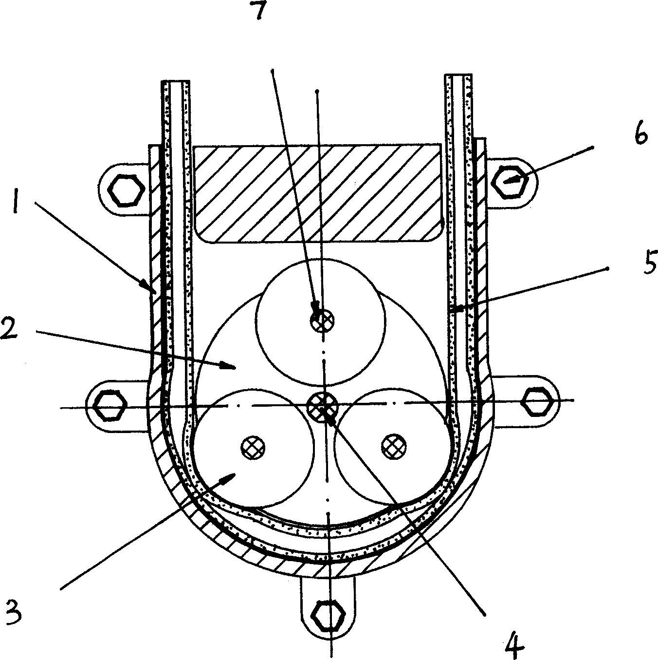
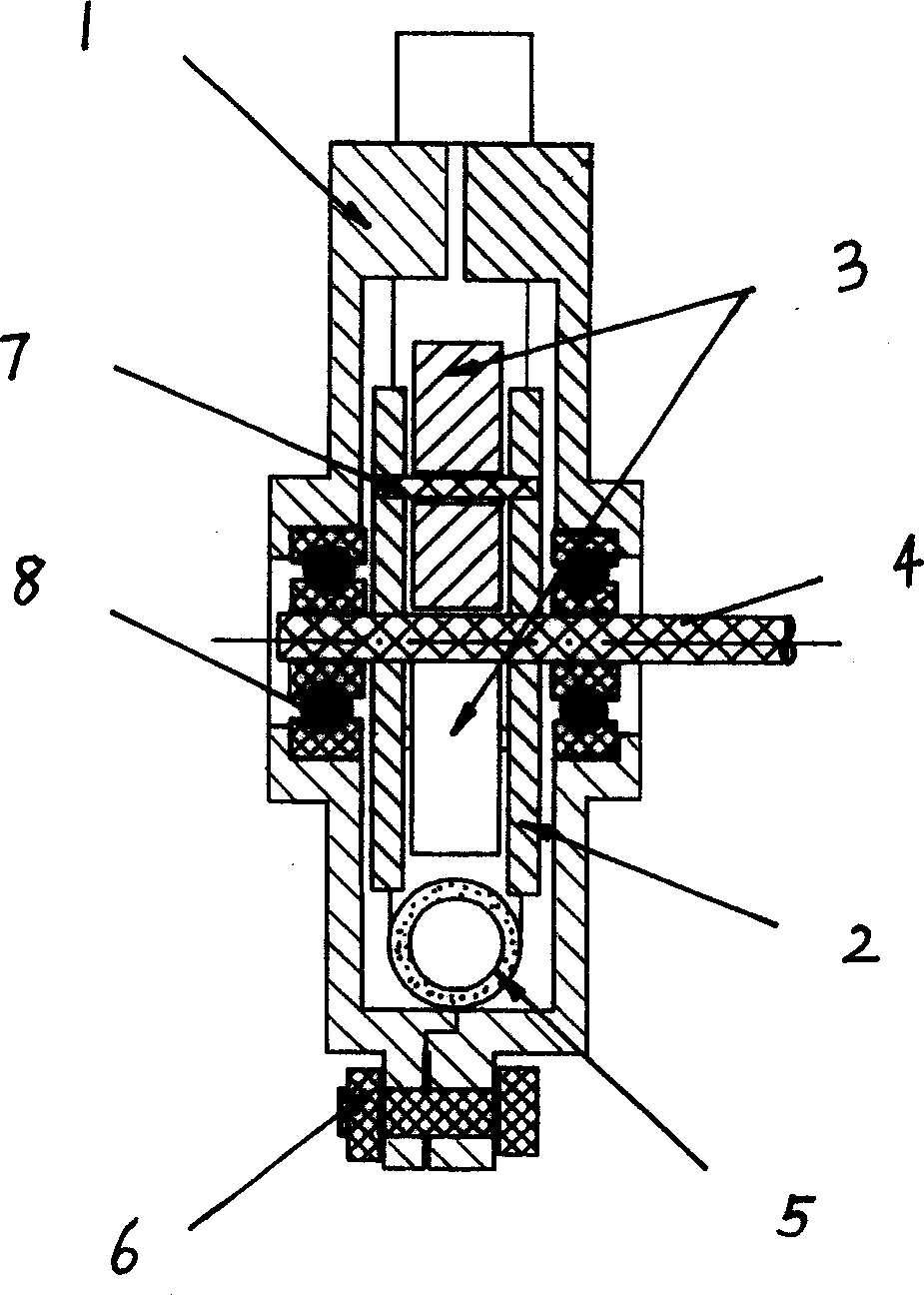
[0013] combine figure 1 and figure 2 , the medical infusion pump of the embodiment includes a pump housing 1 and a rotor 2 . A flexible "U"-shaped tube 5 is pierced in the pump casing 1, and a silicone rubber tube is used. The inner wall of the pump casing 1 is made into a corresponding shape, the outer edge of the "U"-shaped tube 5 is closely attached to the inner wall of the pump casing 1, and three freely rotating rollers 3 are arranged on the circumference of the rotor 2, and the rollers 3 are tightly pressed on the inner wall of the pump casing 1. The inner edge of the "U" shaped pipe 5.

[0014] The axis of the rotor 2 is located at the center of the semicircle in the "U" shape of the "U" tube 5, so as to ensure that the roller 3 is in close contact with the "U" tube 5 when the rotor 2 rotates.

[0015] In the semicircular part of the pump casing 1, the distance from the outer edge of the roller 3 to the inner wall of the pump casing 1 is equal to or less than twice ...


PUM


Abstract

A medical perfusion pump is composed of a casing, a rotor, an elastic U-shaped tube close to the inner surface of said casing, and at least two rollers arranged on the circumference of said rotor and closely pressing said elastic U-shaped tube to divide its internal space into several cavities. When the rotor is rotating, the rollers are moving relatively to the tube to segmentally push the liquid medicine in the tube, making it to flow. Said U-shaped tube is exchangeable for preventing secondary pollution.

Description

technical field [0001] The present invention relates to pumps, especially improvements to medical infusion pumps. Background technique [0002] Existing liquid pumps, especially those used in the medical field, include centrifugal type, piston type, etc. The common feature of these pumps is that various moving parts are arranged in the housing of the pump, such as impellers, pistons, etc. liquid flow. Because the liquid medicine needs to be transported under aseptic conditions, the liquid medicine is easily polluted during the contact process with the machine parts. During secondary use, the cleaning and disinfection work of the pump is complicated, and there is also the problem that the liquid residue in the pump is not easy to eliminate. Contents of the invention [0003] The purpose of the present invention is to provide a medical infusion pump whose part in contact with the medicinal liquid can be easily replaced, so as to solve the problem of secondary pollution. ...

Claims


Application Information

Patent Timeline
Patent Type & Authority Applications(China)
IPC IPC(8): A61M5/142A61M1/00A61M3/00F04C5/00
Inventor 林晓莎沈洁郏妮安娜
Owner 徐嘉
Why Eureka
Try Eureka