Supporting scaffold for bridge construction

A technology for supporting scaffolding and bridge construction, which is applied in the field of supporting scaffolding and construction equipment, can solve the problem that the scaffold is not equipped with anti-fall protection mechanism, and can improve the connection stability, improve the lifting stability, and ensure the tightness of the connection. Effect

Active Publication Date: 2022-07-29
SHANXI LINFEN MUNICIPAL ENG GRP CO LTD
View PDF16 Cites 0 Cited by
  • Summary
  • Abstract
  • Description
  • Claims
  • Application Information

AI Technical Summary

Problems solved by technology

[0006] The purpose of the present invention is to provide a supporting scaffold for bridge construction, which is used to solve the problem that the existing scaffold is not equipped with a corresponding anti-fall mechanism to provide anti-fall protection;

Method used


Image

  • Supporting scaffold for bridge construction
  • Supporting scaffold for bridge construction
  • Supporting scaffold for bridge construction

Examples


Embodiment 1

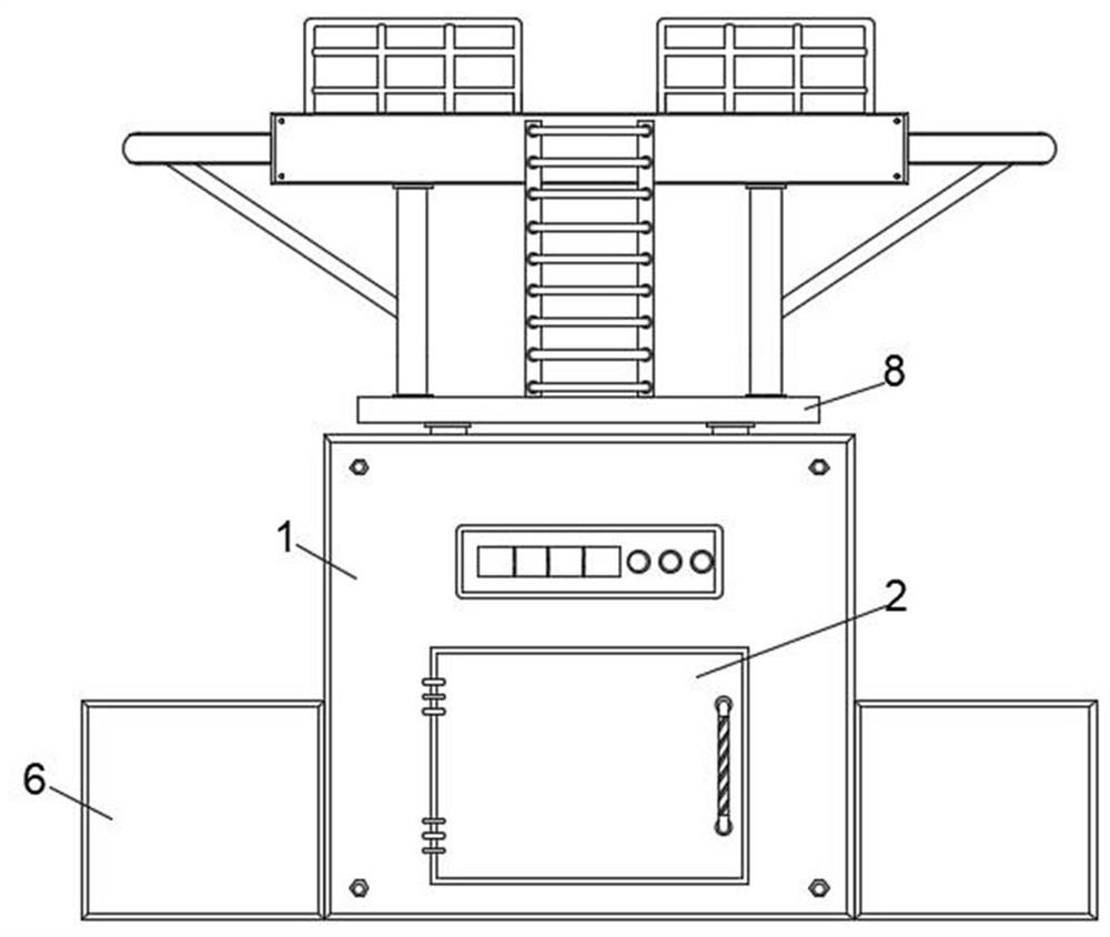
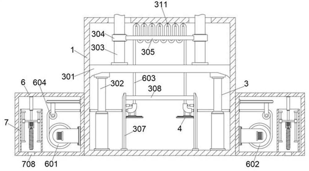
[0041] like Figure 1-2 As shown, a support scaffold for bridge construction includes a support box 1, a box door 2 is arranged on the front of the support box 1, one side of the box door 2 is hinged with the front of the support box 1 through hinges, and the box door 2 is on the other side. A handle is fixedly installed on the front of one side, and a jacking mechanism 3 is arranged inside the support box 1. The jacking mechanism 3 includes a support plate 301 slidably connected between the inner side walls of the support box 1. The bottom of the support plate 301 is connected to the support box. 1. Two symmetrical hydraulic cylinders 302 are fixedly installed between the inner bottom walls. The hydraulic cylinders 302 are used to lift the support plate 301 to provide support for the support column 303 and the balance arm. The top of the support plate 301 is fixedly installed with evenly distributed supports Column 303, the top of the support column 303 passes through the inn...

Embodiment 2

[0049] see Figure 8 As shown, the front of the support box 1 is provided with a processor, and the processor is communicatively connected with an acquisition module, a storage module, a controller, a risk monitoring module and a tensile detection module;

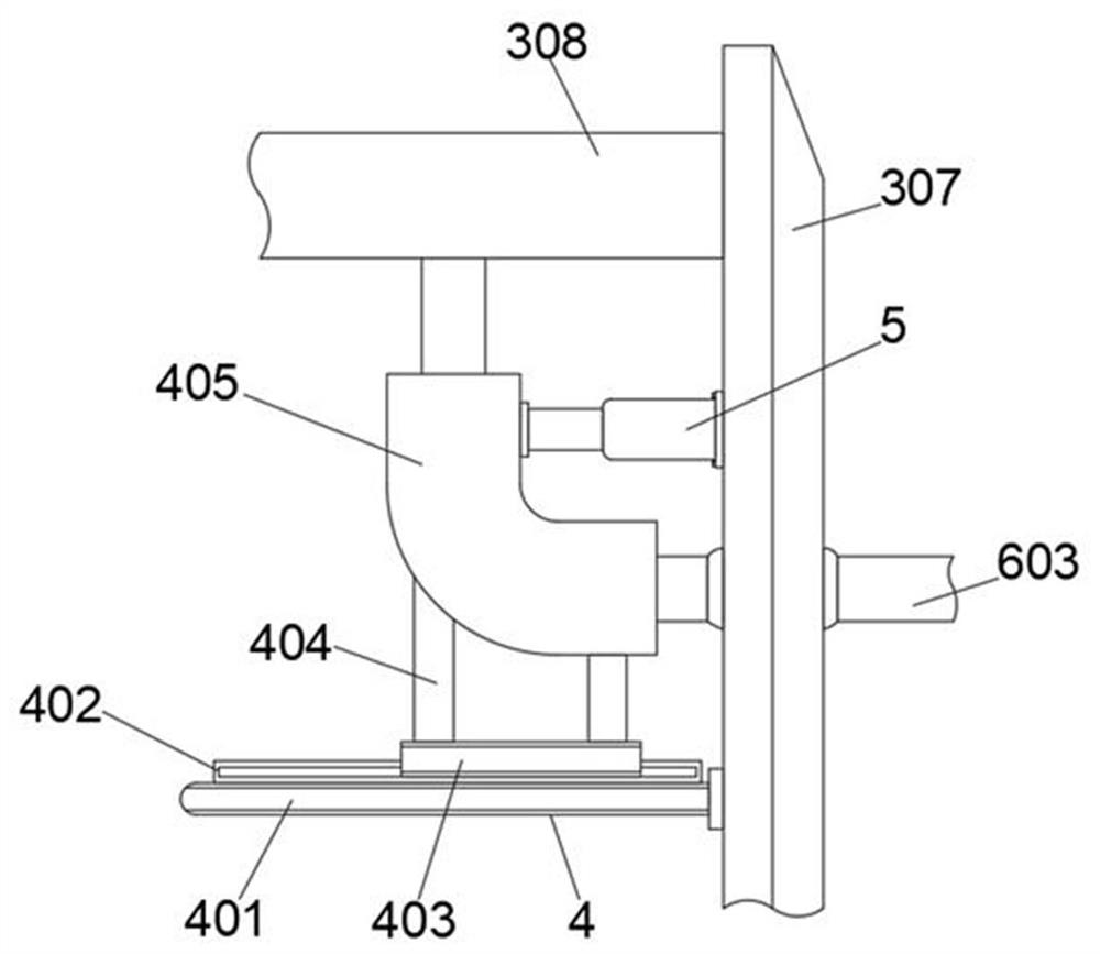
[0050] The acquisition module includes a wind speed sensor, a dust sensor and a displacement sensor arranged on the slider 403, which are arranged on the working platform 802;

[0051] The storage module is used to store data;

[0052] The controller is electrically connected to the hydraulic cylinder 302 and the input end of the first drive motor;

[0053]The risk monitoring module is used for risk monitoring of the environment of the construction site. The specific process of risk monitoring includes: obtaining the wind speed value at the working platform 802 in real time through the wind speed sensor and marking it as the operating wind speed value FY; obtaining the real-time wind speed value at the working platform 802...


PUM


Abstract

The invention belongs to the field of bridge construction, relates to a construction equipment technology and aims to solve the problem that an existing scaffold is not provided with a corresponding anti-falling mechanism to provide anti-falling protection, in particular to a supporting scaffold for bridge construction and an operation system of the supporting scaffold, the supporting scaffold comprises a supporting box body, and a jacking mechanism and a pulling detection mechanism are arranged in the supporting box body; the jacking mechanism comprises a bearing plate slidably connected between the inner side walls of the bearing box body, two symmetrical hydraulic cylinders are fixedly installed between the bottom of the bearing plate and the inner bottom wall of the bearing box body, the hydraulic cylinders are used for jacking up the bearing plate to support the bearing columns and the balance arms, the evenly-distributed bearing columns are fixedly installed on the top of the bearing plate, and the balance arms are fixedly installed on the top of the bearing plate. The top of the supporting column penetrates through the inner top wall of the supporting box body and extends to the outside of the supporting box body; according to the working platform, the steel cable penetrates through the first wrapping hole and the locking ring to lock the balance plate, so that the connection tightness of the balance plate and the supporting box body is guaranteed, and the lifting stability of the working platform is improved.

Description

technical field [0001] The invention belongs to the field of bridge construction and relates to construction equipment technology, in particular to a supporting scaffold for bridge construction. Background technique [0002] Bridge engineering refers to the work process of bridge survey, design, construction, maintenance and verification, as well as the science and engineering technology to study this process. It is a branch of civil engineering. The development of bridge engineering mainly depends on the needs of transportation for it. [0003] Scaffolding refers to the various supports erected on the construction site for workers to operate and solve vertical and horizontal transportation. A general term in the construction industry refers to the use of external walls, interior decoration or high storey heights on construction sites where direct construction cannot be performed, mainly for construction purposes. Personnel work up and down or maintenance of peripheral safe...

Claims


Application Information

Patent Timeline
Patent Type & Authority Applications(China)
IPC IPC(8): E01D21/00
CPCE01D21/00
Inventor 曹召成王彩云梁建秀李官斌袁斌峰
Owner SHANXI LINFEN MUNICIPAL ENG GRP CO LTD
Why Eureka
Try Eureka