
UHPC precast arched girder combined type aqueduct

A combined and aqueduct technology, applied in irrigation pipelines, applications, buildings, etc., can solve problems such as difficult construction, and achieve the effect of reducing construction difficulty, ensuring integrity, and relaxing construction conditions

Pending Publication Date: 2020-11-20
SOUTH CHINA UNIV OF TECH
View PDF0 Cites 1 Cited by
  • Summary
  • Abstract
  • Description
  • Claims
  • Application Information

AI Technical Summary

Problems solved by technology

[0006] The purpose of the present invention is to provide a UHPC prefabricated arch-beam combined aqueduct in order to overcome the problems of high construction difficulty of the combined aqueduct body in the prior art.

Method used


Image

  • UHPC precast arched girder combined type aqueduct
  • UHPC precast arched girder combined type aqueduct
  • UHPC precast arched girder combined type aqueduct

Examples


Embodiment 1

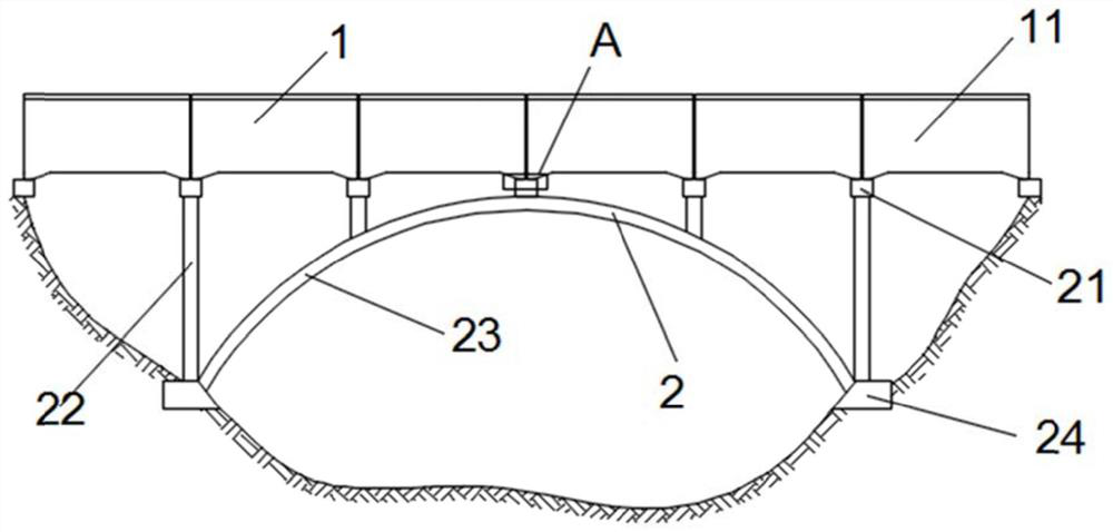
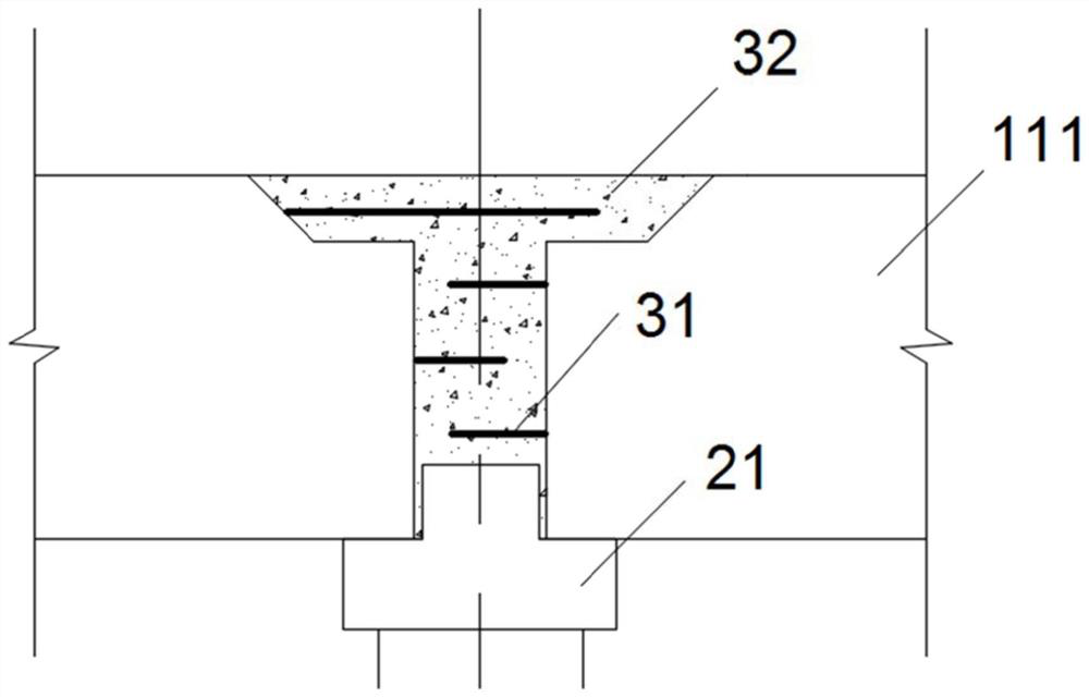
[0025] Such as figure 1 As shown, a UHPC prefabricated arch-beam combined aqueduct includes an arch structure 2 and an aqueduct body 1. The end rib 111 of the aqueduct body 1 is hinged to the top of the arch structure 2, which can reduce the size of the aqueduct body 1 and the arch structure 2. The friction between the struts 22. The main body of the aqueduct 1 includes multiple sections of prefabricated tank bodies 11 , and a wet joint structure 3 is provided between two adjacent prefabricated tank bodies 11 . The groove-arch stiffness ratio β is the ratio of the bending stiffness EJ of the main section 1 of the aqueduct to the compressive stiffness EA of the section 23 of the arch (ie β=EJ / EA). . The axis equation of the structure 2 on the arch is (where: x and y 0 is the coordinate on the axis of the arch body, f is the height of the rise, and l is the span), and the rise-span ratio (f / l) of the arch body 23 of the structure 2 on the arch is 1 / 5. The main body 1 of th...

Embodiment 2

[0036] In this embodiment, except that the following technical features are different, other technical features are the same as in Embodiment 1:

[0037] The rise-span ratio (f / l) of the arch body 23 of the arch structure 2 in this embodiment is 1 / 14 instead of 1 / 5.

[0038] In the ultra-high performance concrete in this embodiment, the steel fibers are directly 0.4 mm fine steel fibers instead of 0.15 mm fine steel fibers.

[0039] In this embodiment, carbon fibers are added instead of polyvinyl alcohol fibers and high elastic modulus polyethylene fibers, and the volumetric dosage of carbon fibers is 0.6% instead of 0.1%.

[0040] The tangent of the end tangent of the arch body 23 in this embodiment is replaced by 0.35 by 1.38.

[0041] In this embodiment, the length of the exposed end of the steel bar 31 is 550 mm instead of 250 mm; in the same horizontal plane, the width of the wet joint structure 3 is 100 mm longer than the projected length of the exposed end of the steel...


PUM


Abstract

The invention discloses a UHPC precast arched girder combined type aqueduct. The UHPC precast arched girder combined type aqueduct comprises an arched structure and an aqueduct main body, wherein endribs of the aqueduct main body are hinged with the top end of the arched structure; the aqueduct main body comprises a plurality of sections of precast slot bodies; a wet jointing structure is arranged between every two adjacent precast slot bodies; the wet jointing structure comprises reinforcing steel bars and ultrahigh-performance concrete layers; the fixed ends of the reinforcing steel bars are fixedly connected to the precast slot bodies; exposed ends of the reinforcing steel bars are connected to the ultrahigh-performance concrete layers; and the bottoms of the ultrahigh-performance concrete layers are connected to the top end of the arched structure. The stress characteristics of the arched girder combined type aqueduct structure are sufficiently utilized, high-strength ultrahigh-performance concrete is adopted, applicable span is 150-500 m, applicable span of the conventional concrete girder arched combined type aqueduct is 50-120m which is 3-4 times that of a conventional arched girder type aqueduct.

Description

technical field [0001] The invention relates to the technical fields of building materials and hydraulic engineering, in particular to a UHPC prefabricated arch-beam combined aqueduct. Background technique [0002] An aqueduct is an overhead water delivery structure that transports water across complex terrain such as canals, roads, mountain rushes, and valley mouths. It is one of the most widely used intersecting buildings in canal systems. In addition to water, industrial water, and water transfer across river basins, it can also be used for flood drainage and diversion. According to its supporting structure type, stress state, and load transfer mode, aqueducts are divided into beam type, rib arch type, truss type, combined type, and cable-stayed type. Among them, the "arch-beam combined structure aqueduct" is developed from the truss arch. The tank body is used as the upper chord of the truss arch, and the vertical bar (bent frame) and the lower chord (arch) form a whole...

Claims


Application Information

Patent Timeline
Patent Type & Authority Applications(China)
IPC IPC(8): E02B13/00
CPCE02B13/00
Inventor 谢宇轩杨医博林捷鑫覃文倩刘俊君任续锋段政岐郎功誉郭文瑛王恒昌
Owner SOUTH CHINA UNIV OF TECH
Learn More